What is workholding and why is it important?
Workholding is how stock is held during operations on CNC mills and lathes. Unlike in CAD, parts don’t just float in 3D space. Something needs to grab onto the part to keep it from moving or flying off when the machine removes material. Workholding is one of the most important considerations when it comes to manufacturing. You can have perfect tools and toolpaths, but that doesn’t matter if there isn’t a surface to hold onto the part. Workholding also presents clearance challenges, can leave marks on your part, and therefore must be considered throughout the entire design and manufacturing process.
Types of part surfaces to clamp on
For workholding, there are 3 main types of surface finishes to consider before clamping down onto the stock.
- Bandsaw cut (least preferred for clamping): A surface that has been cut with a bandsaw. Bandsaws leave the worst finish and sometimes a large burr on the bottom edge. This burr must be removed, and the resulting surface should be prepped beforehand for clamping. Is strongly preferred to clamp in snap jaws.
- Extruded: Raw stock from a factory is usually extruded. While the surfaces may look flat and parallel at a glance, in reality, they usually are not. So again, snap jaws are strongly preferred for clamping onto this type of surface.
- Machined (most preferred for clamping): A pair of surfaces that have been machined on a CNC mill and are known to be parallel. Since these surfaces are guaranteed to be parallel, they can be put inside flat jaws.
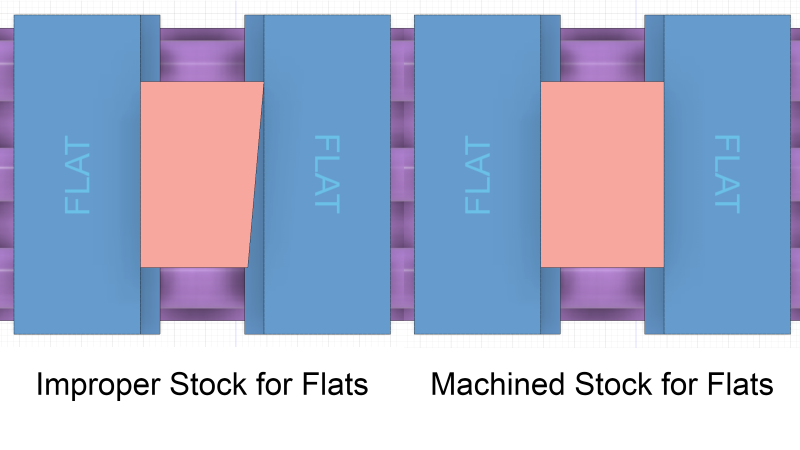
The reason we need properly-parallel surfaces to use the flat jaws is due to clamping area, as demonstrated in the exaggerated view below. If the two sides clamped are not parallel, then one side will have full contact, and the other side will have only a single point of contact. This reduces the effective clamping area and your part may fly out of the jaws during machining.
What workholding should I pick?
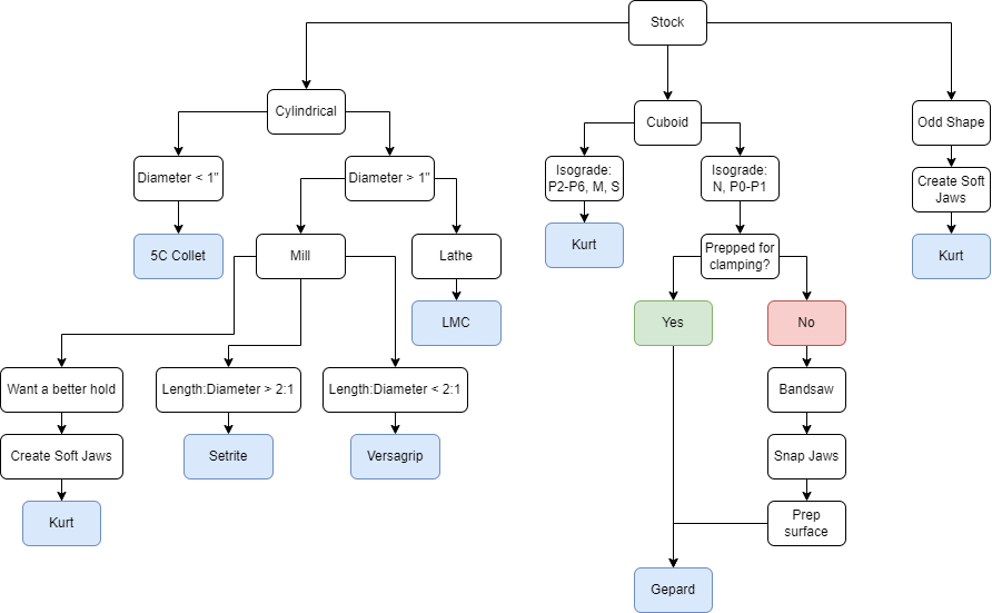
There are a variety of workholding options available at BIDC. The following simplified flowchart roughly shows the thought process behind workholding. However, there is a lot more that goes into it, so please reference the table for actual constraints and values. The table also contains pictures to give you a better visual understanding of how each option works. All workholding is also modeled in the BIDC Fusion 360 Team in the Workholdings and Stocks folder.
Workholding for CNC Mills
| Vice | Jaw | Description | Constraints | How it Clamps |
Gepard 300 | This vice comes standard on the VF2 and the VF4, and can be placed on the UMC as well. | Must be torqued down to 60 ft-lbs for proper clamping. |  How the jaws slide into the vice | |
Short Snap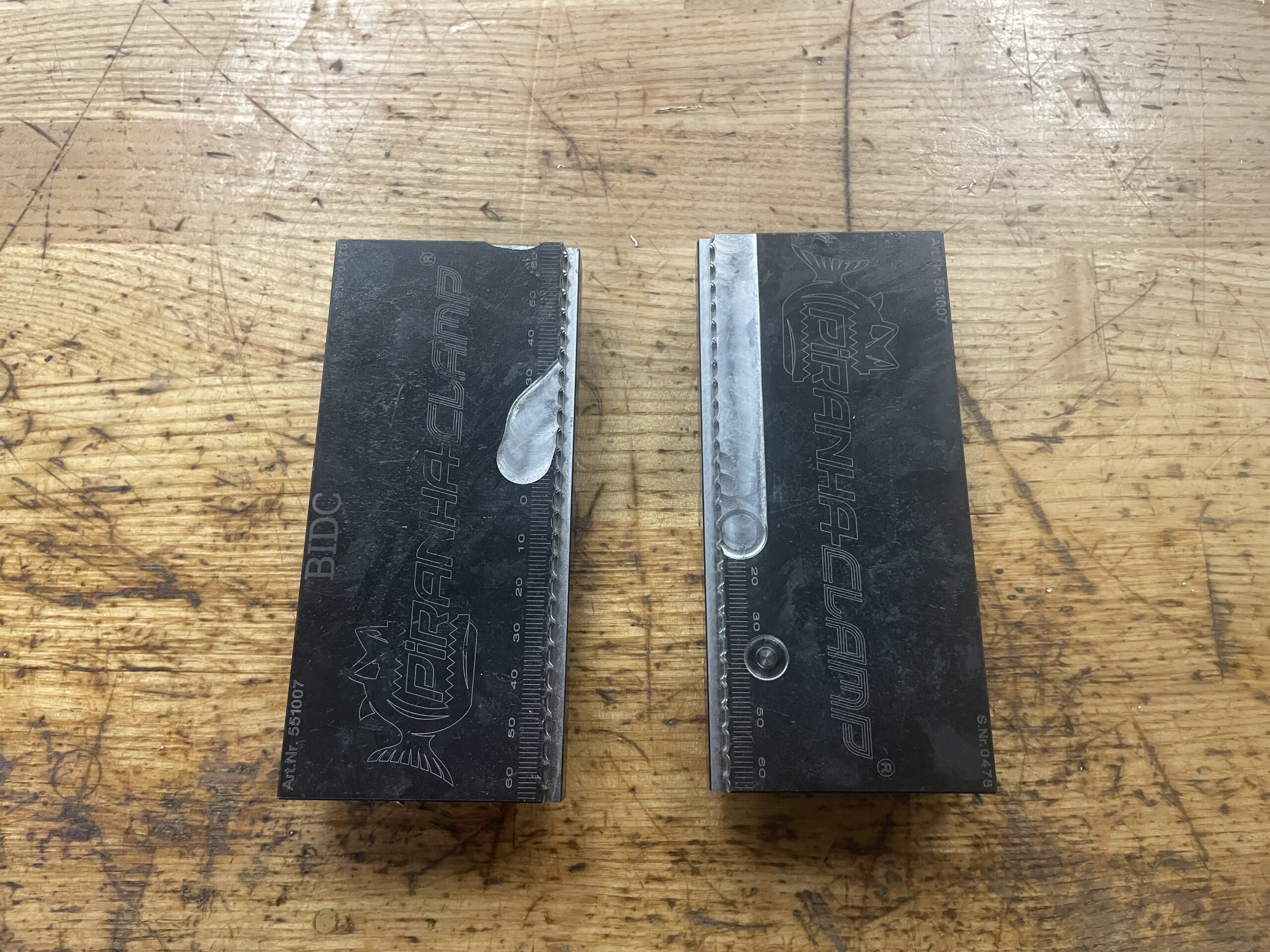 | Has serrated teeth that dig into the part. Can grip onto rough surfaces. | Maximum of 6″ between the shortest sides of the part. Leaves marks on the part. | 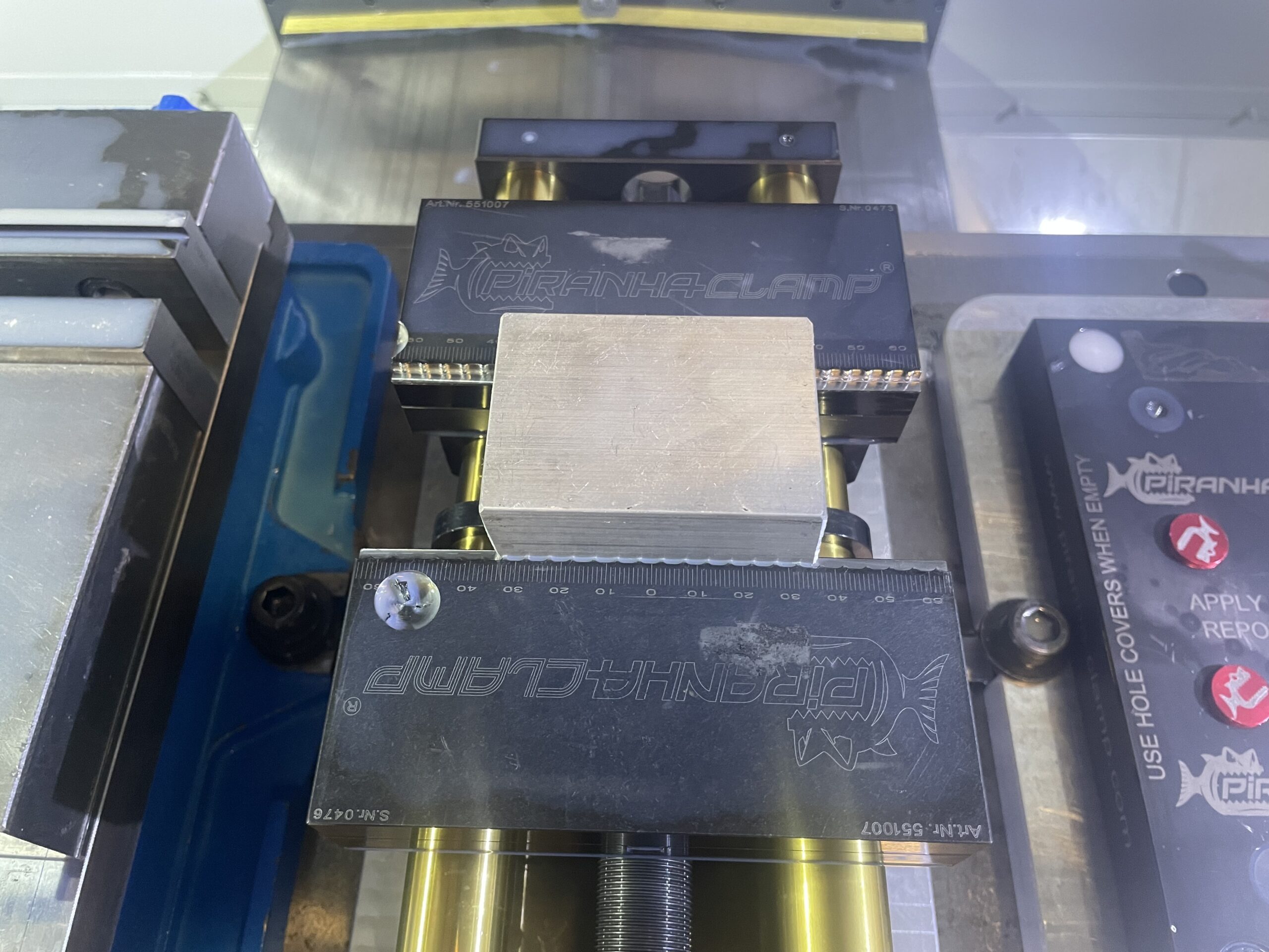 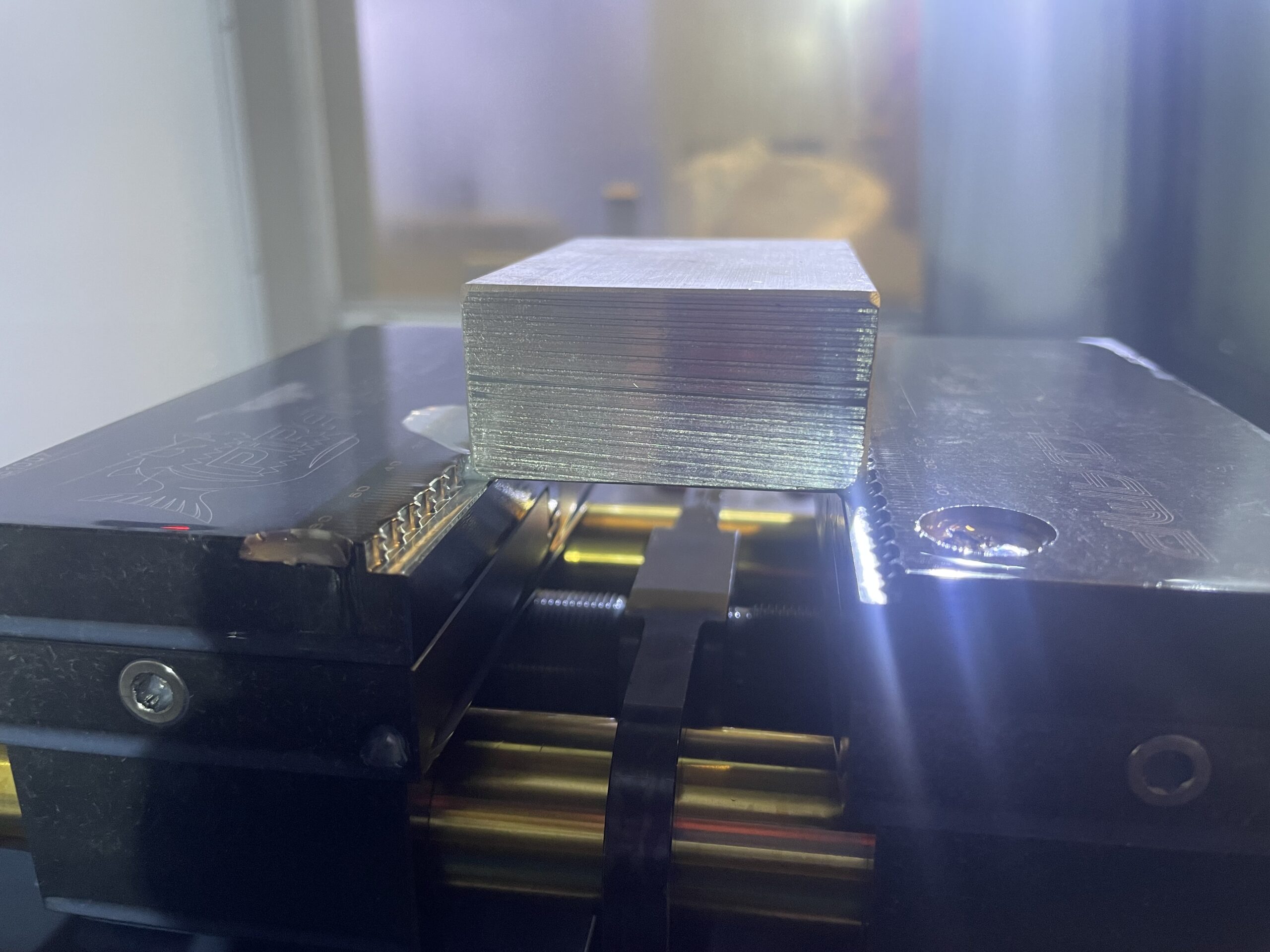 | |
Short Flat | Flat clamping sides allow clamping onto parallel surfaces without leaving marks. | Maximum of 5″ between shortest sides of the part. Requires machined surfaces. |   | |
Long Snap | Has serrated teeth that dig into the part. Can grip onto rough surfaces. | Maximum of 9.5″ between shortest sides of the part, or a minimum of 4″ between the longest sides. Leaves marks in part |  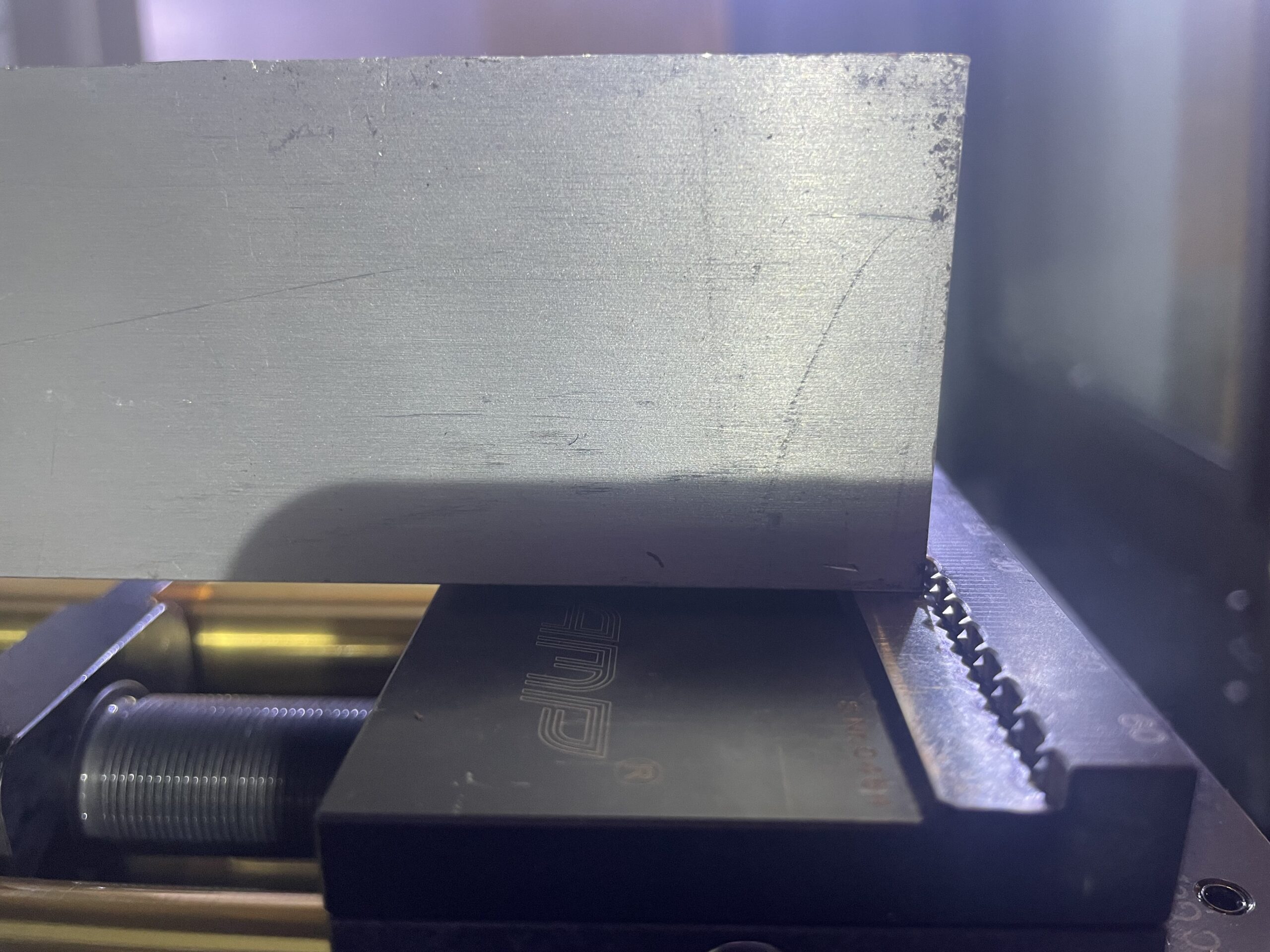 | |
Long Flat | Flat clamping sides allow clamping onto parallel surfaces without leaving marks. | Maximum of 9.5″ between the shortest sides of the part, or a minimum of 4″ between the longest sides. Requires machined surfaces. |   | |
Versagrips | These jaws can clamp on round parts from the outside (OD Clamping). The 4 black studs can be rotated and shifted to correctly match the outer diameter of the part. | Minimum diameter of 2” and maximum diameter of 8.5″. Can only OD Clamp, no ID clamping. |   | |
Soft Jaws | Custom jaws cut out of a blank. Used only if all other workholding options cannot work for your part. | Must machine the jaws before using them. |  | |
Gepard 170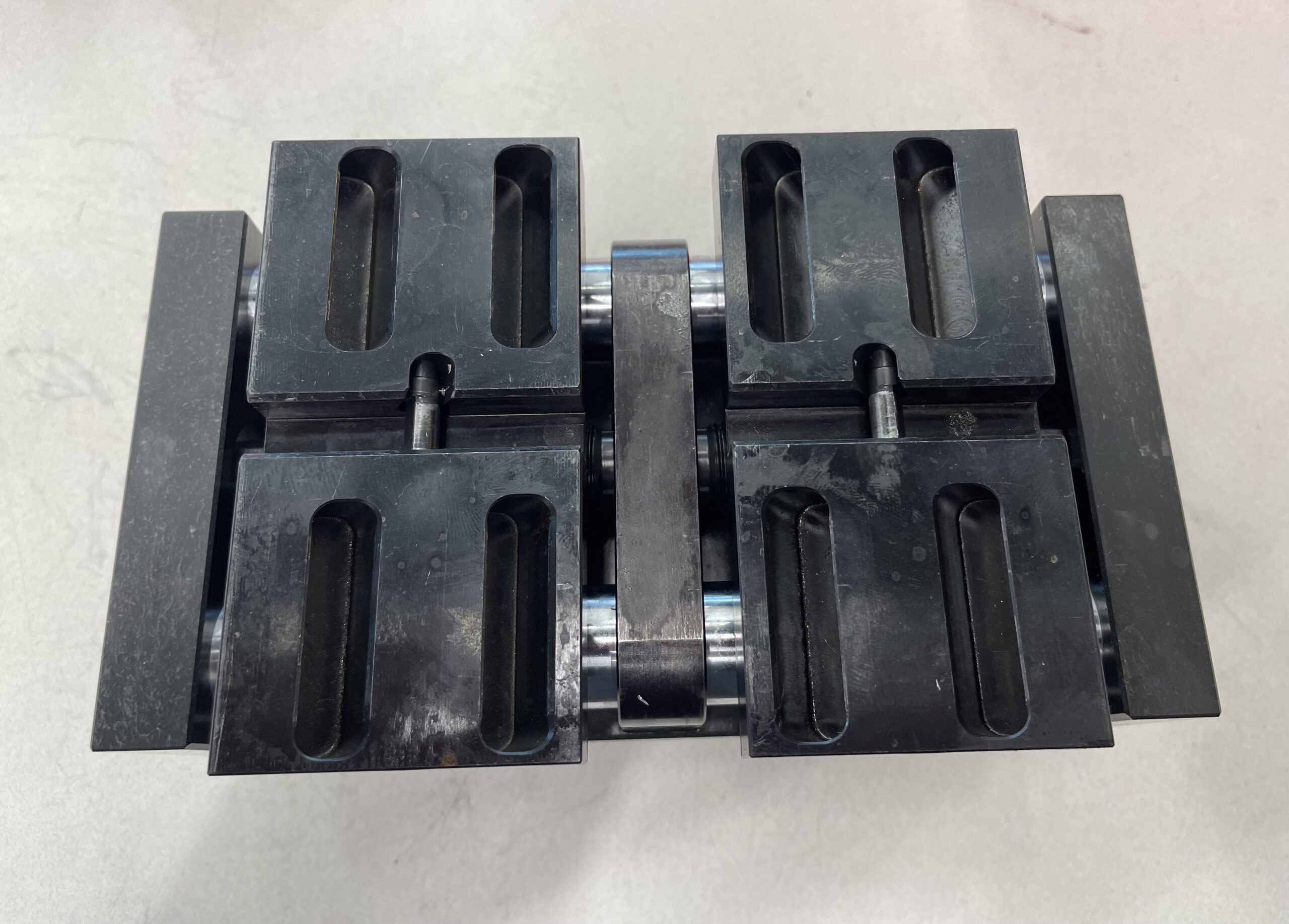 | This vice is nearly identical to the Gepard 300 except that it is smaller. | Must be torqued down to 40 ft-lbs for proper clamping. |  How the jaws slide into the vice | |
Short Snap | Has serrated teeth that dig into the part. Can grip onto rough surfaces. | Maximum of 2.5″ between shortest sides of the part. Leaves marks on the part. | 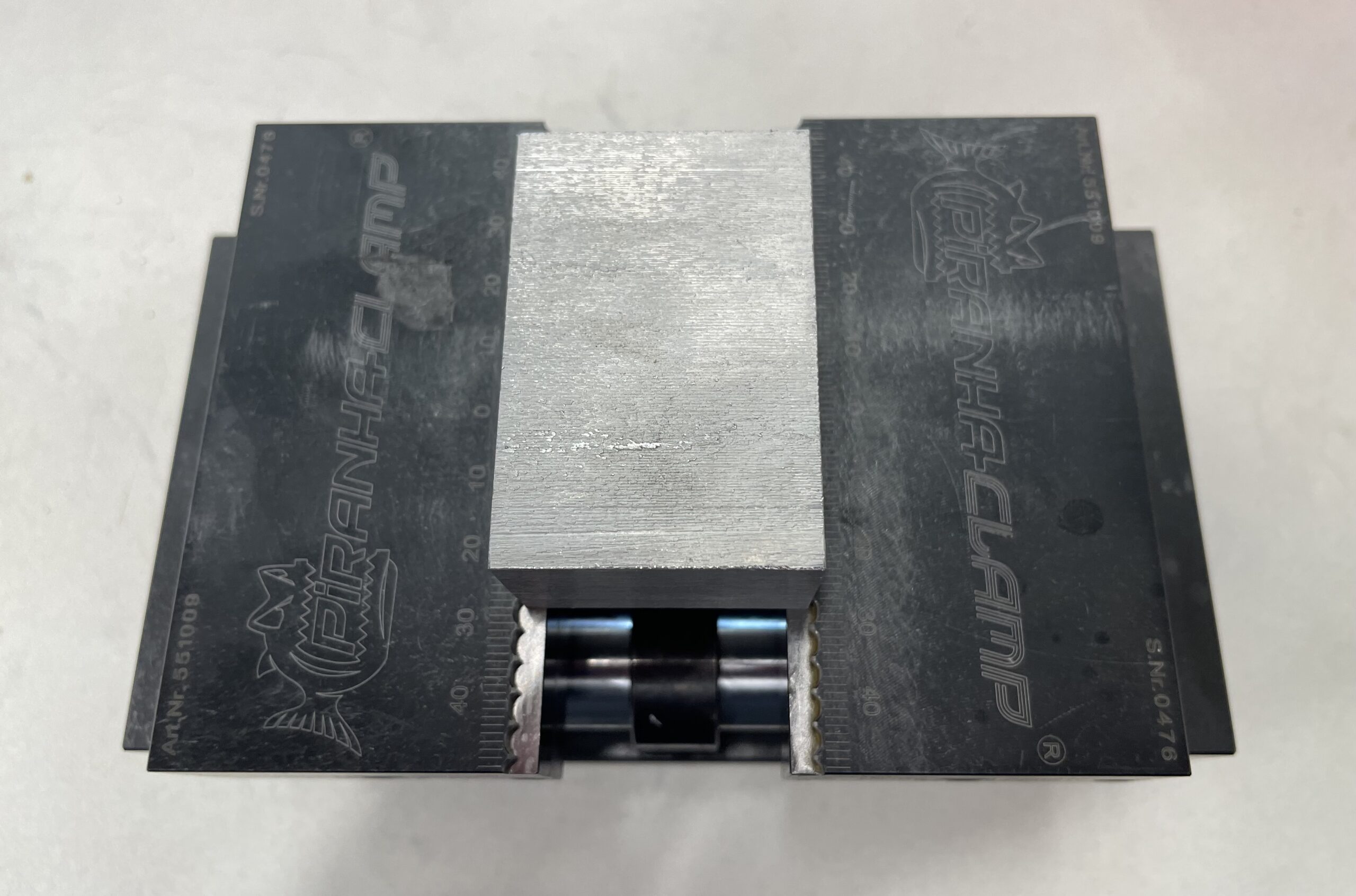 | |
Short Flat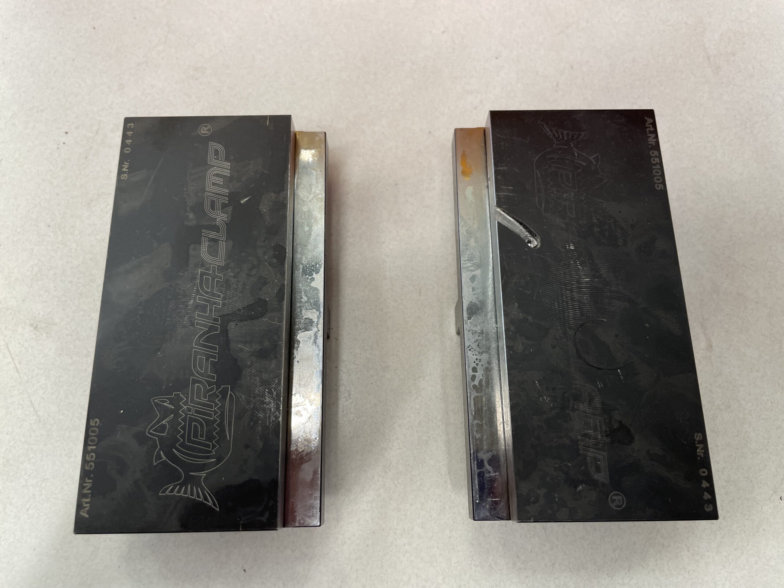 | Flat clamping sides allow clamping onto parallel surfaces without leaving marks. | Maximum of 2.5″ between shortest sides of the part. Requires machined surfaces. |  | |
Long Snap | Has serrated teeth that dig into the part. Can grip onto rough surfaces. | Maximum of 5″ between shortest sides of the part, or a minimum of 3.25 between the longest sides. Leaves marks in part. |  | |
Long Flat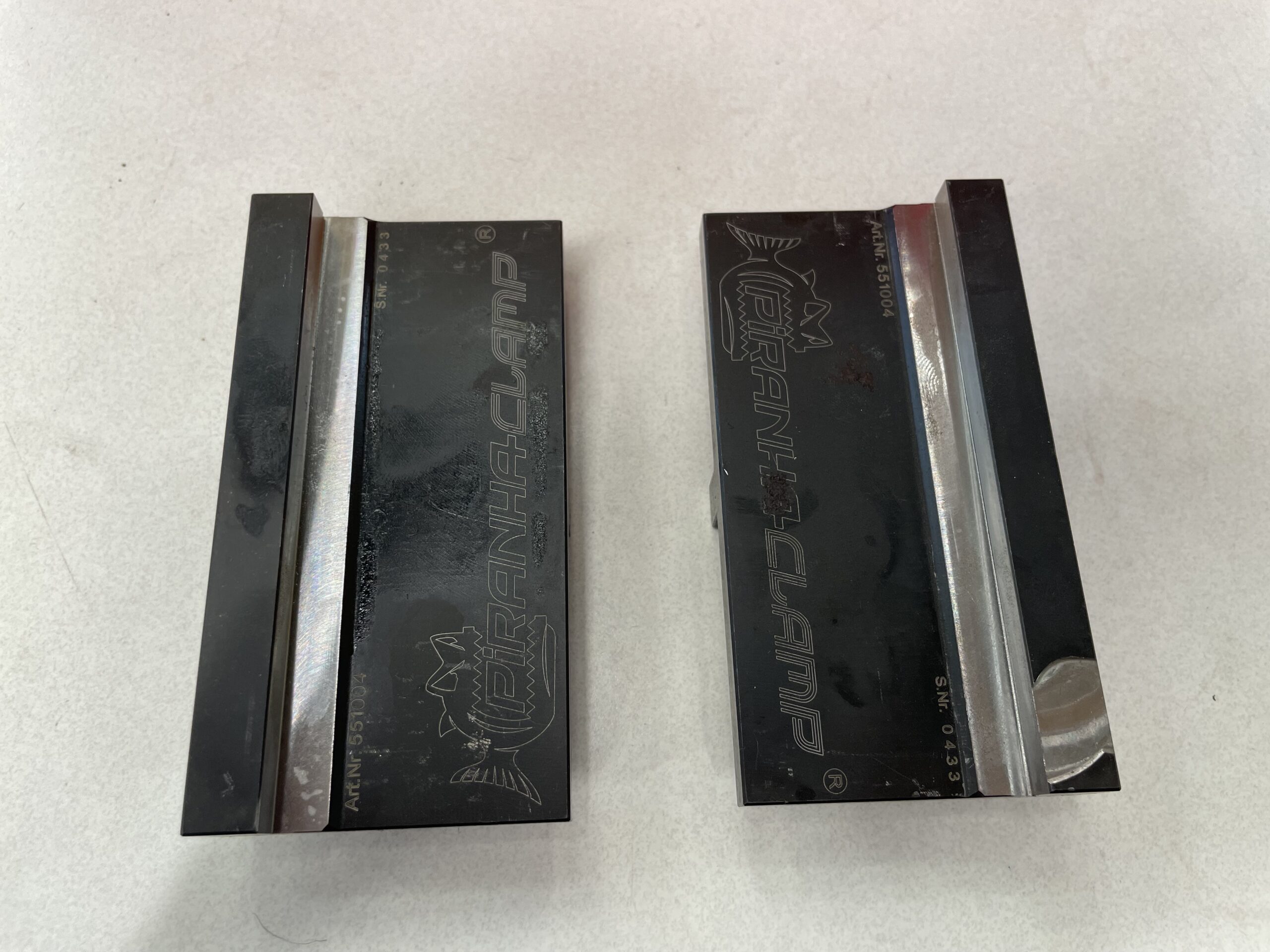 | Maximum of 5″ between the shortest sides of the part, or a minimum of 3.25″ between the longest sides. Requires machined surfaces. | 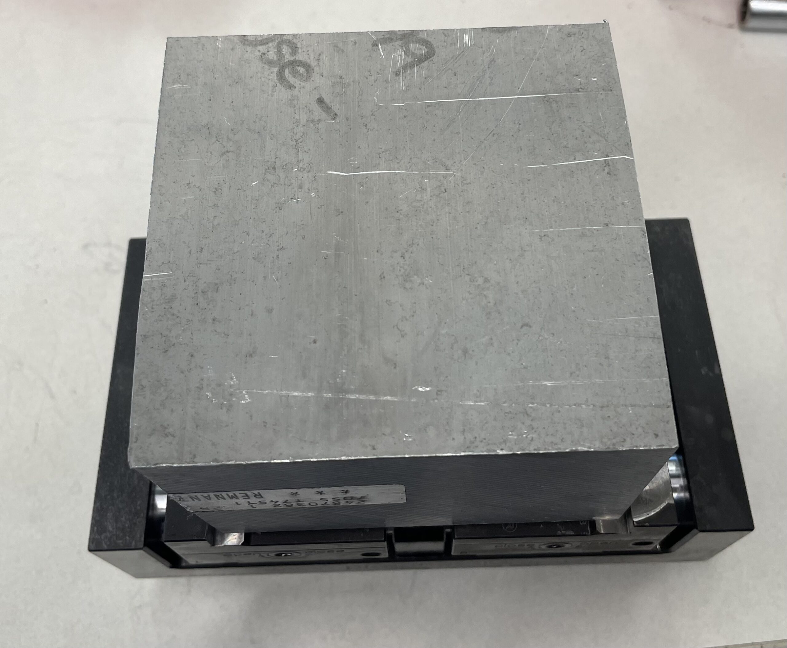 | ||
Soft Jaws | Custom jaws cut out of a blank. Used only if all other workholding options cannot work for your part. | Must machine the jaws before using them. | 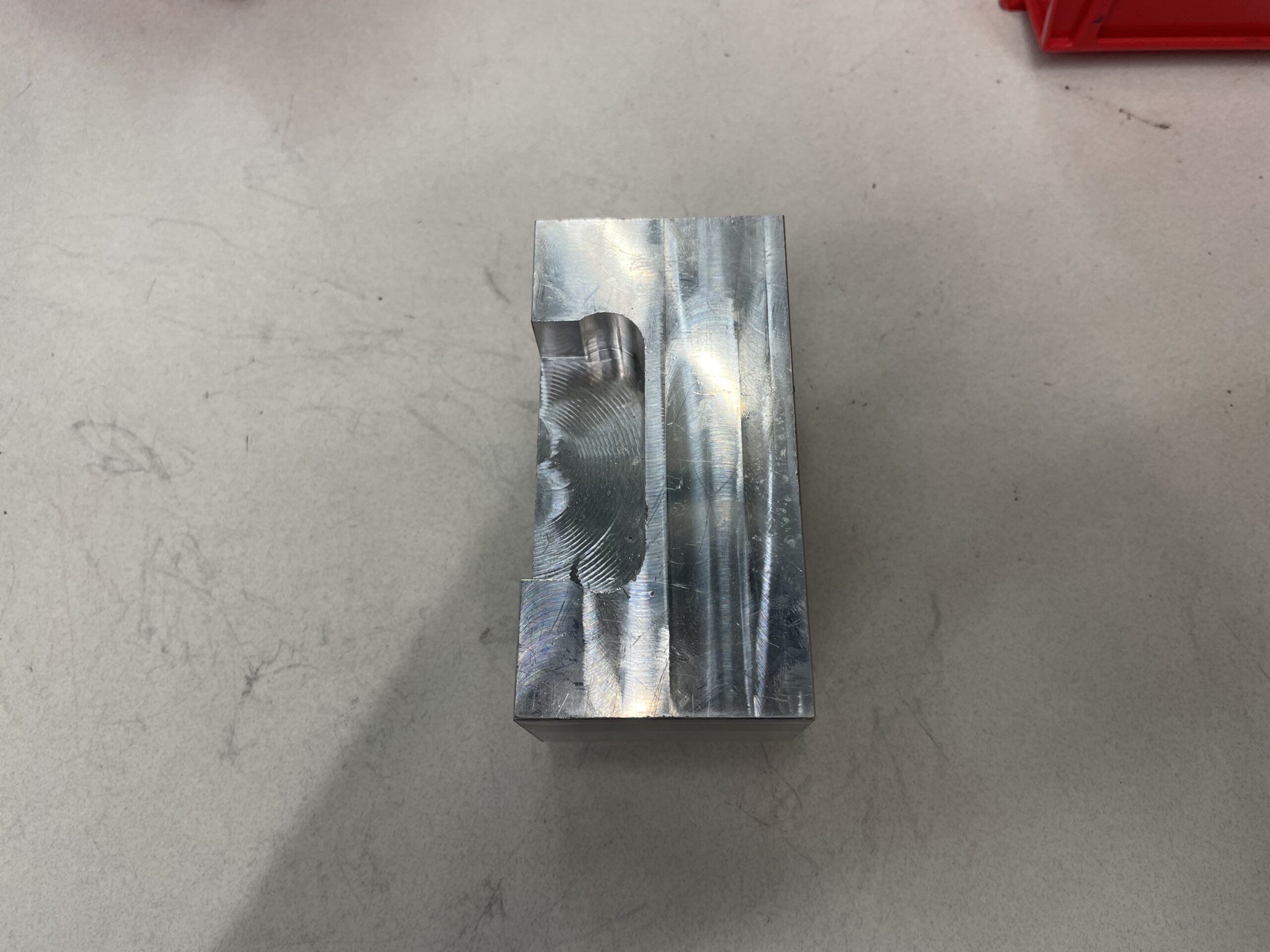 | |
Kurt Vice | A larger, more rigid vice compared to the Gepards that is also standard on the VF2 and VF4. | Typically requires parallels to get the correct part height. Refer to the list at the bottom of the page for available parallel heights.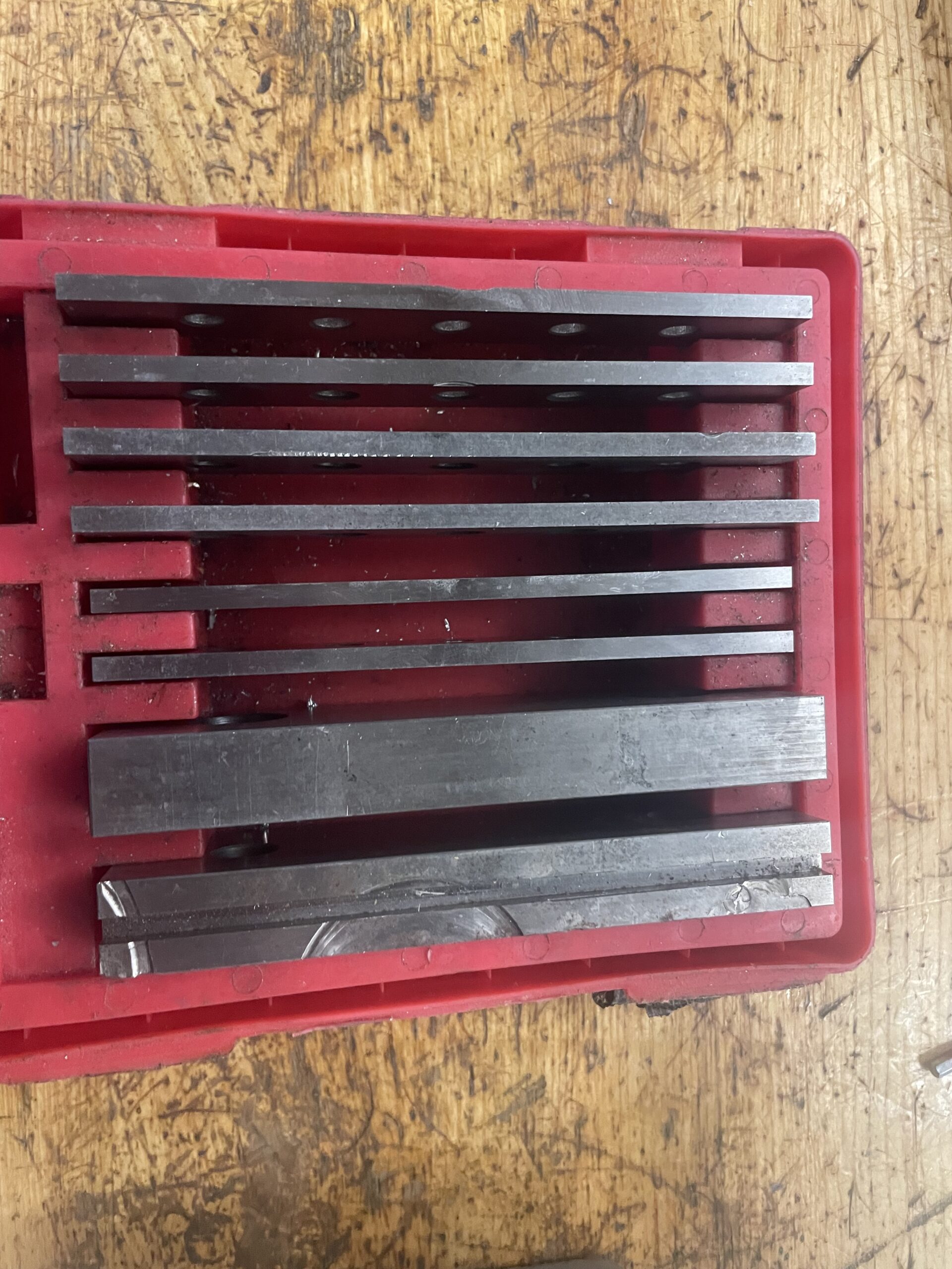  | Parallels vary in height as seen in the picture, and are magnetic, sticking to the vice. | |
Talongrip  | Snap jaws for the Kurt. Has serrated teeth that dig into the part. Can grip onto rough surfaces. | Maximum of 8.75″ between shortest sides of the part. Leaves marks in part. |   | |
Flats 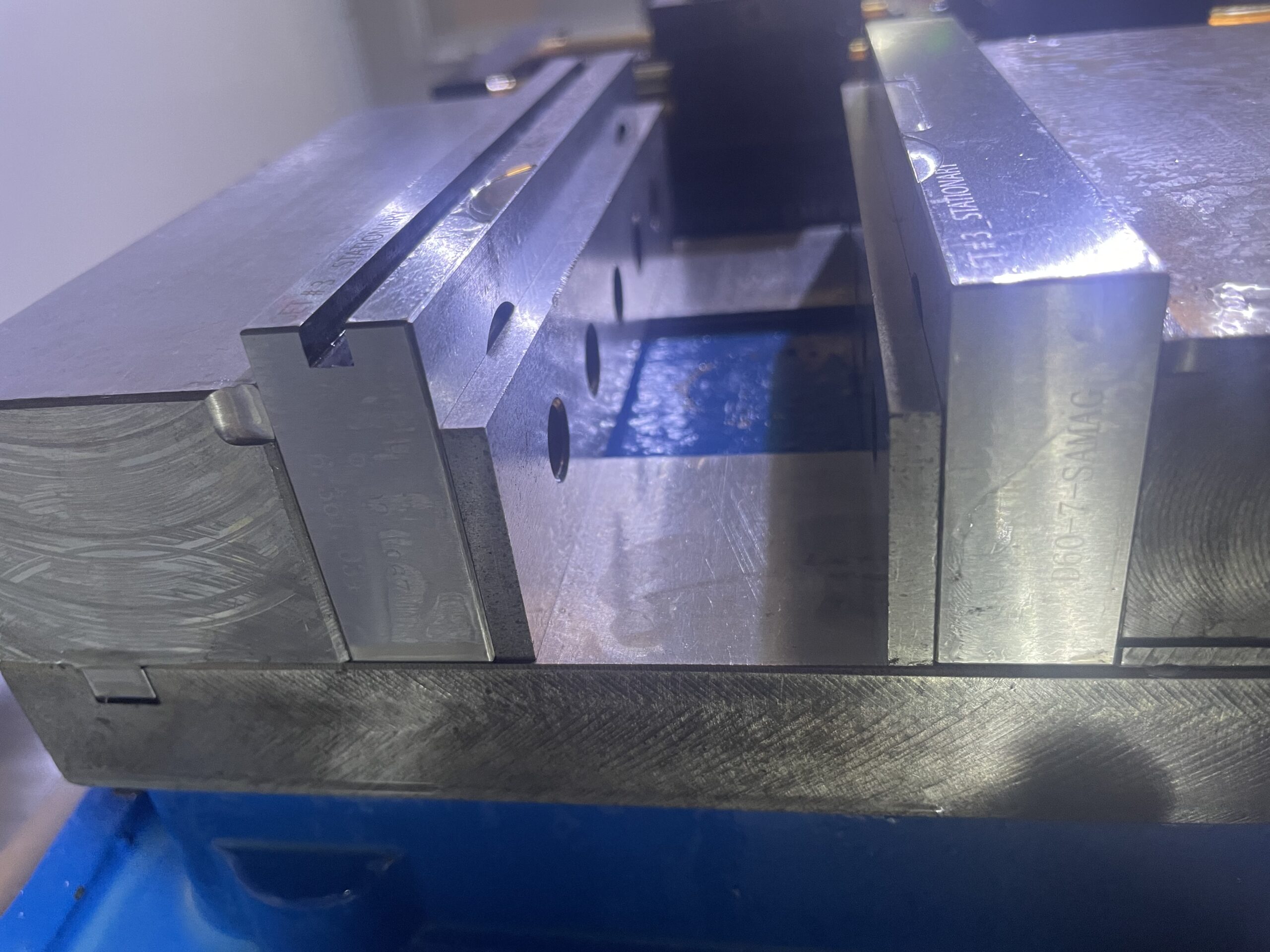 | Flat for the Kurt Vice. | Maximum of 8.75″ between shortest sides of the part. Requires machined surfaces and usually parallels. |   | |
Versagrip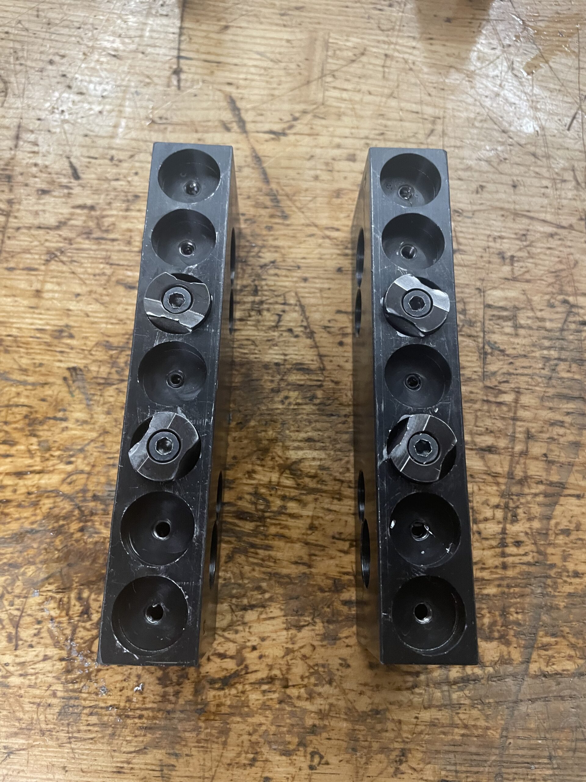  | Versagrip for the Kurt that can OD and ID Clamp. The 4 black studs can be rotated and shifted to correctly match the diameter of the part. | Maximum of 9″ for OD clamping. |  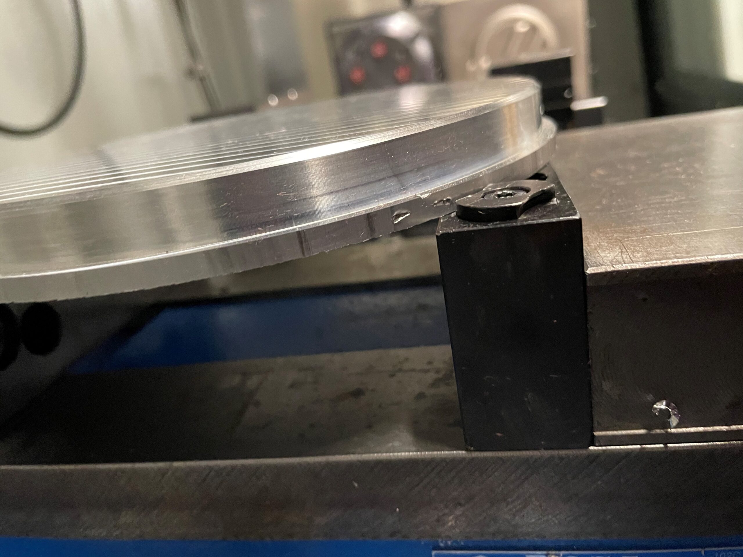 | |
Dovetail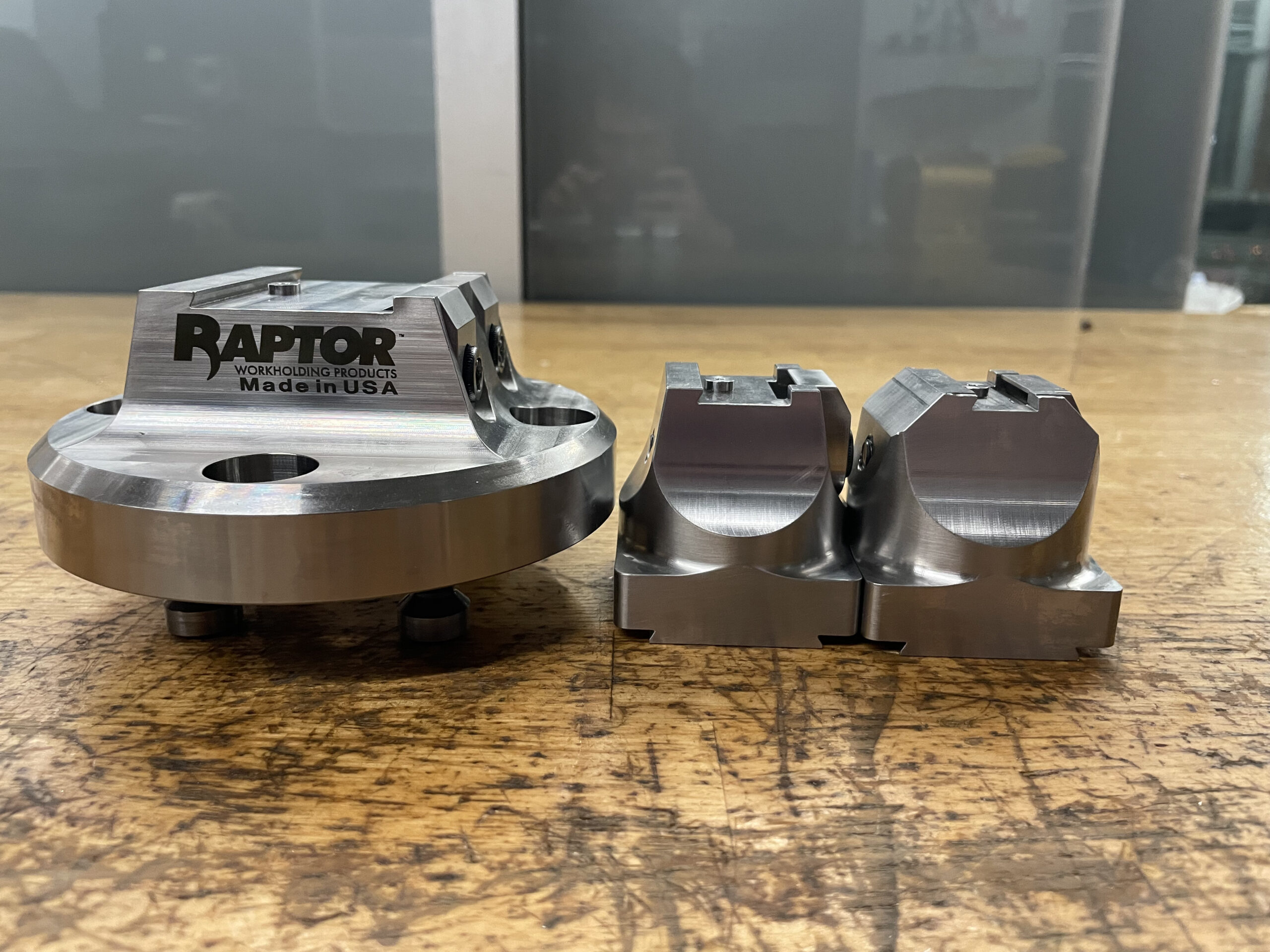  | Clamps with an angled edge and a centering pin. Provides good hold and typically used on the UMC 5-axis. Can access 5 sides of the part for machining. | The minimum width of your dovetail must be the width of the dovetail fixture itself. The entire jaw needs to be used for proper clamping |   | |
0.5″ Dovetail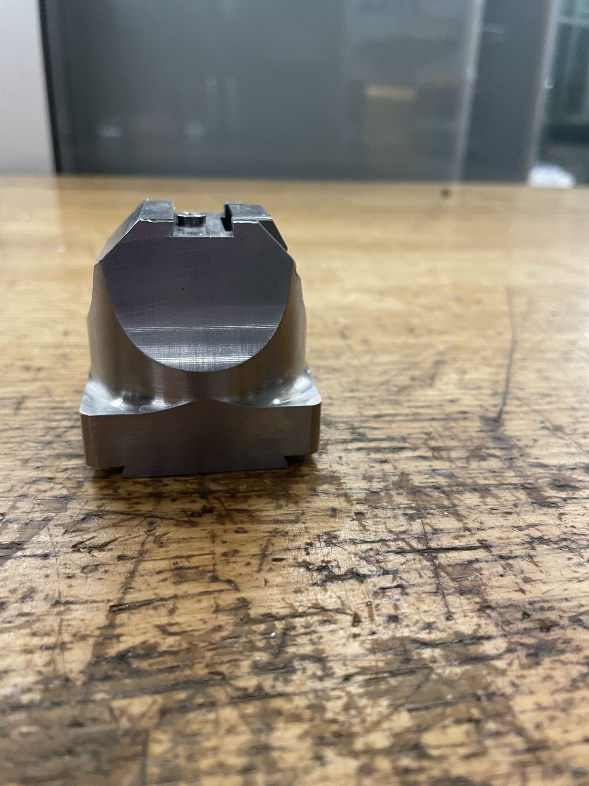 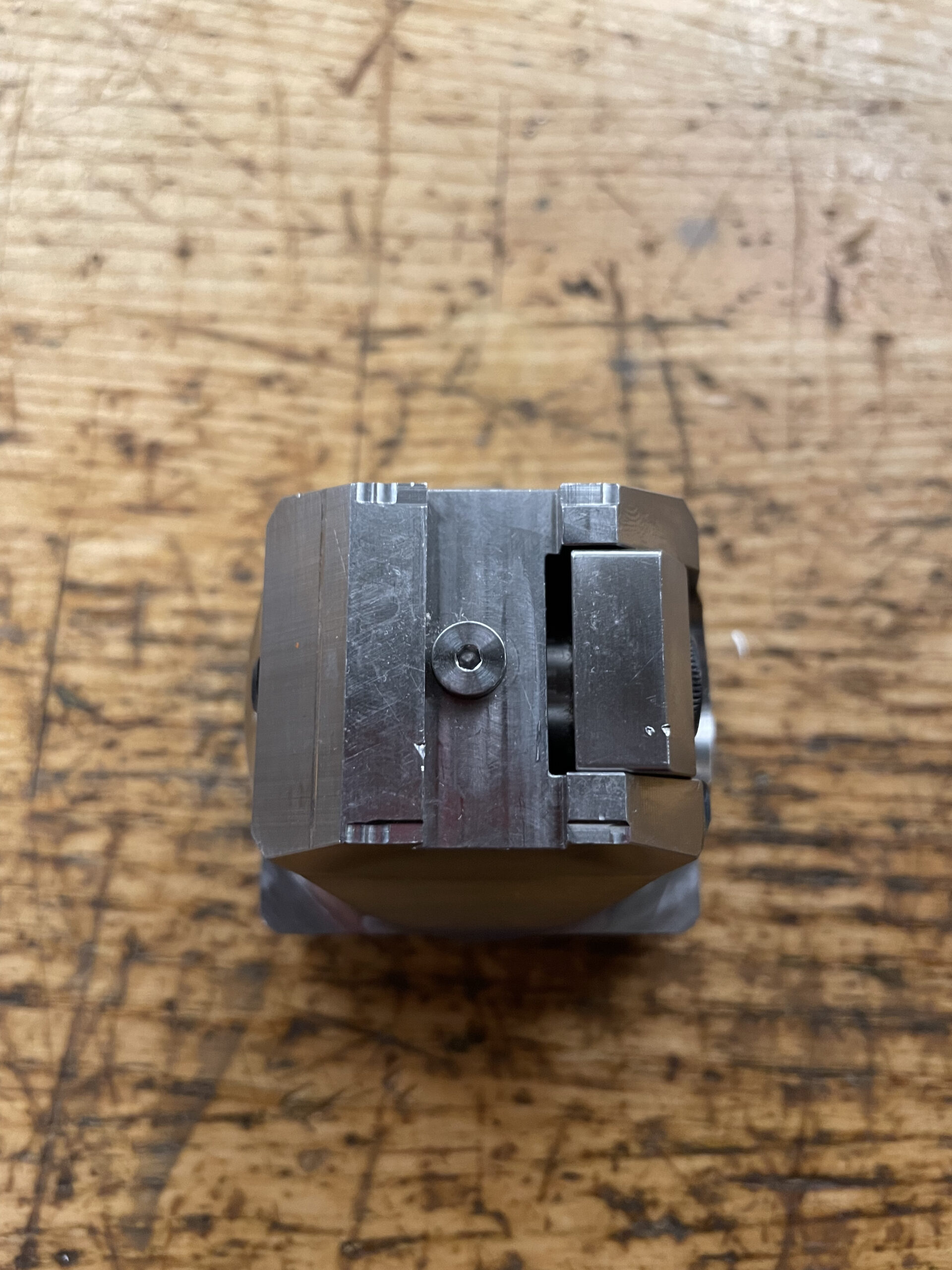 | Smallest size dovetail. | Requires stock prep before it can clamp. | ||
0.75″ Dovetail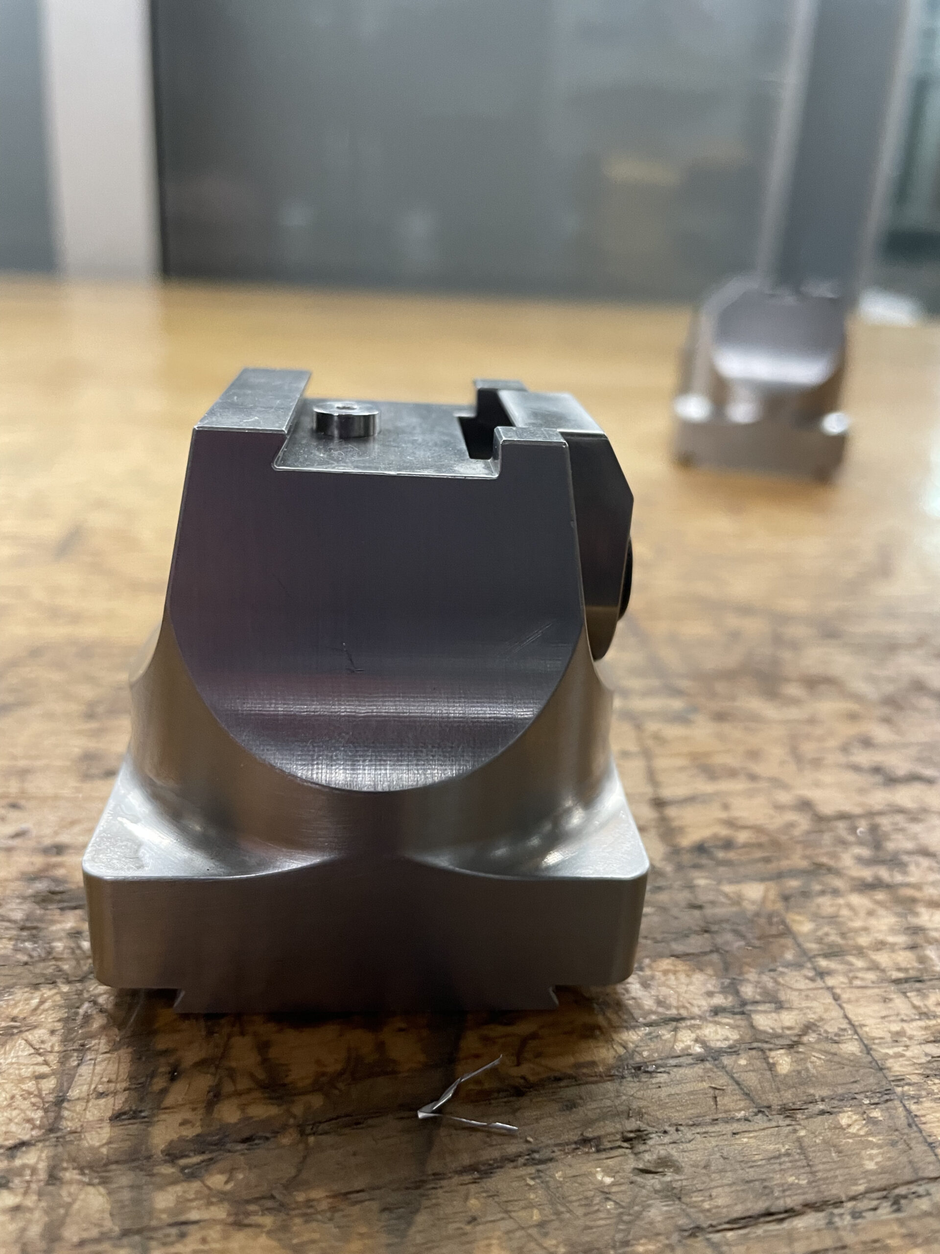 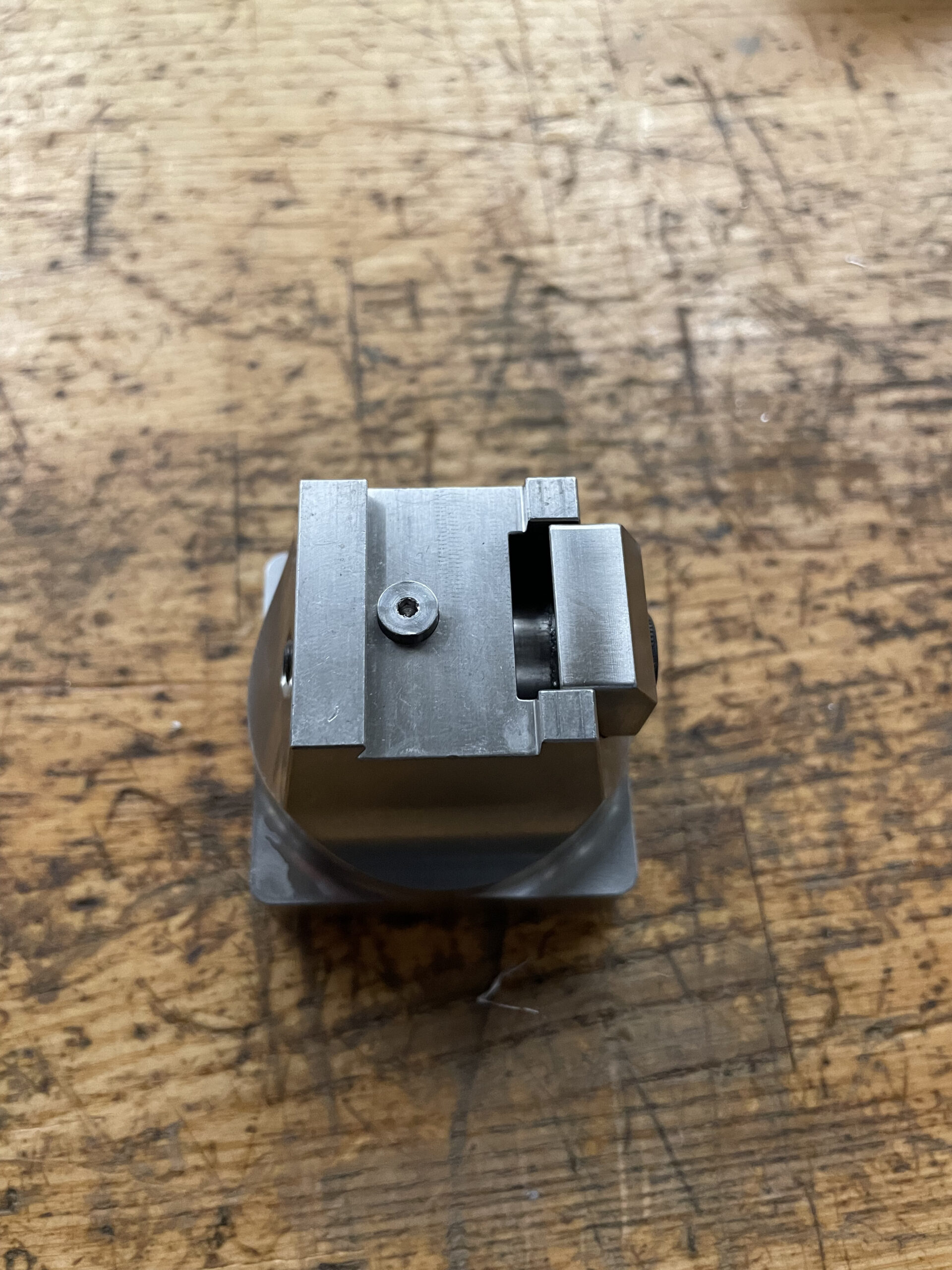 | Medium size dovetail. | Requires stock prep before it can clamp. | ||
1.5″ Dovetail  | Largest size dovetail. | Requires stock prep before it can clamp. | ||
Setrite 3-Jaw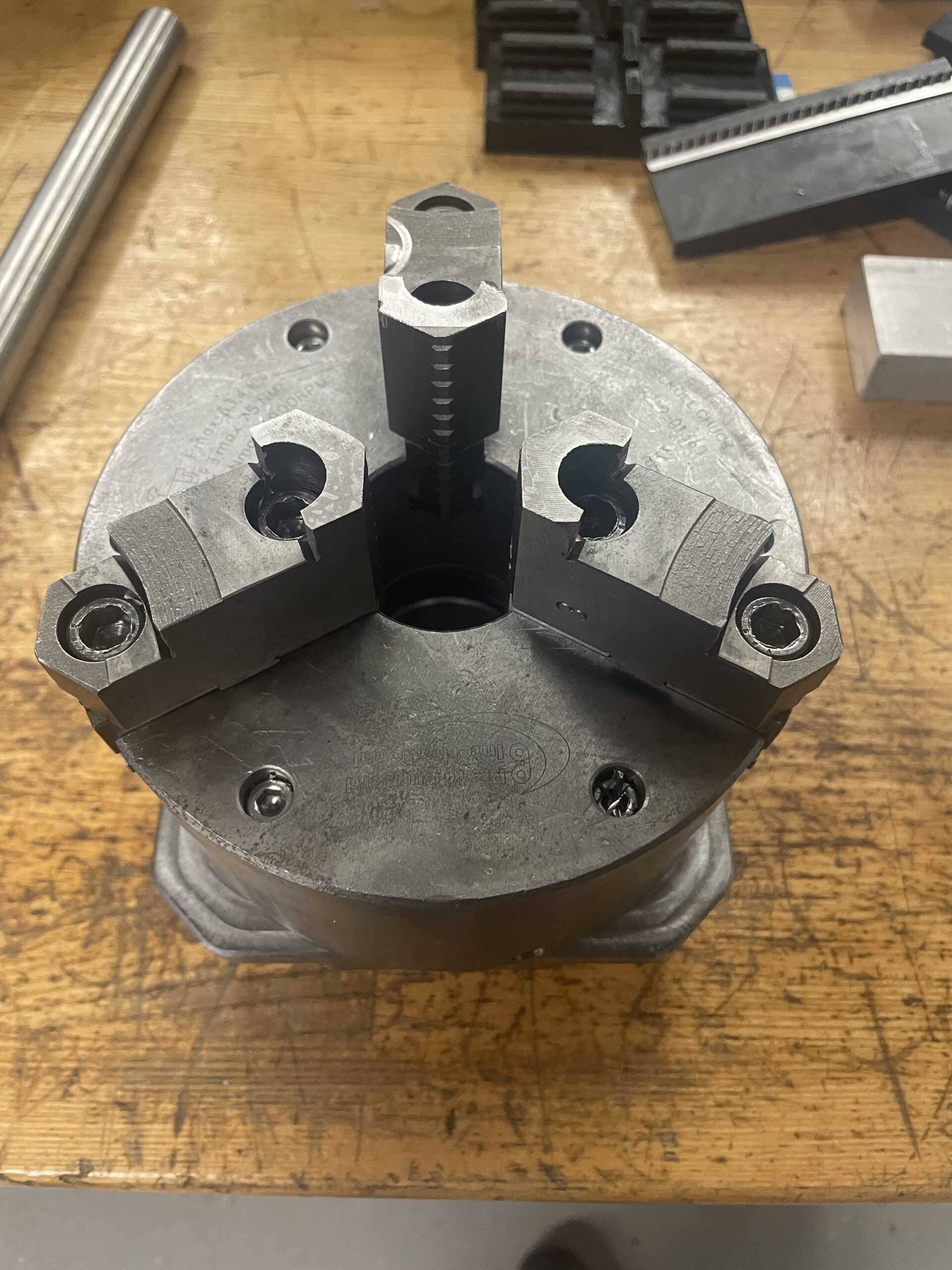 | A 3-jaw clamp for the mill. Attaches to the zero point plate, or can be placed in the Kurt. | |||
| OD | Clamps the outside of the stock. Make sure to rotate the jaws if necessary to best match the diameter of the part. | Maximum stock diameter of 8″.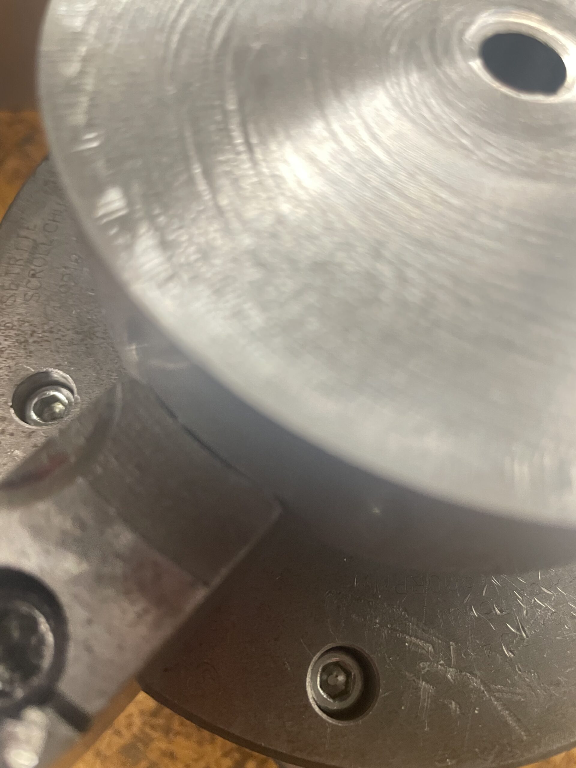 Matching to correct step diameter to maximize clamping area. | 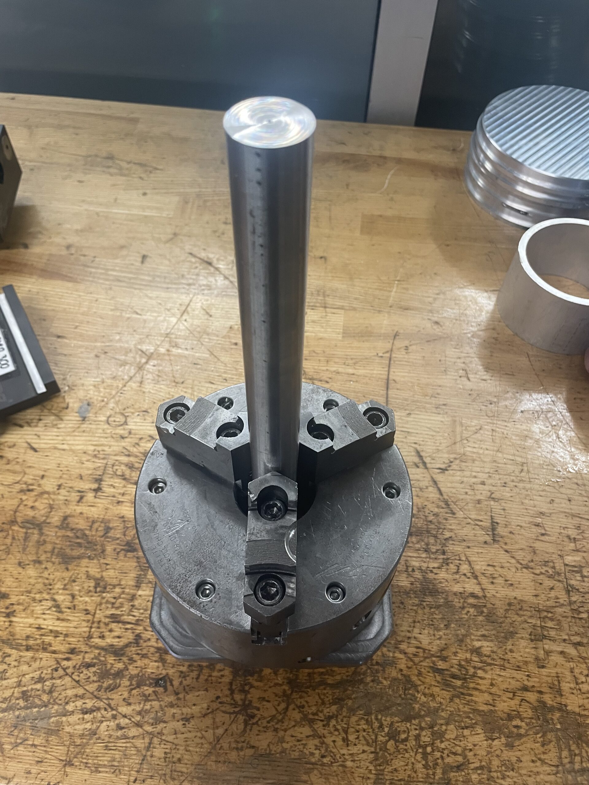  | |
| ID | Clamps the inside of the stock. | Minimum inner stock diameter of 2″, maximum inner stock diameter of 8″. |   | |
VF4 Fixture Plate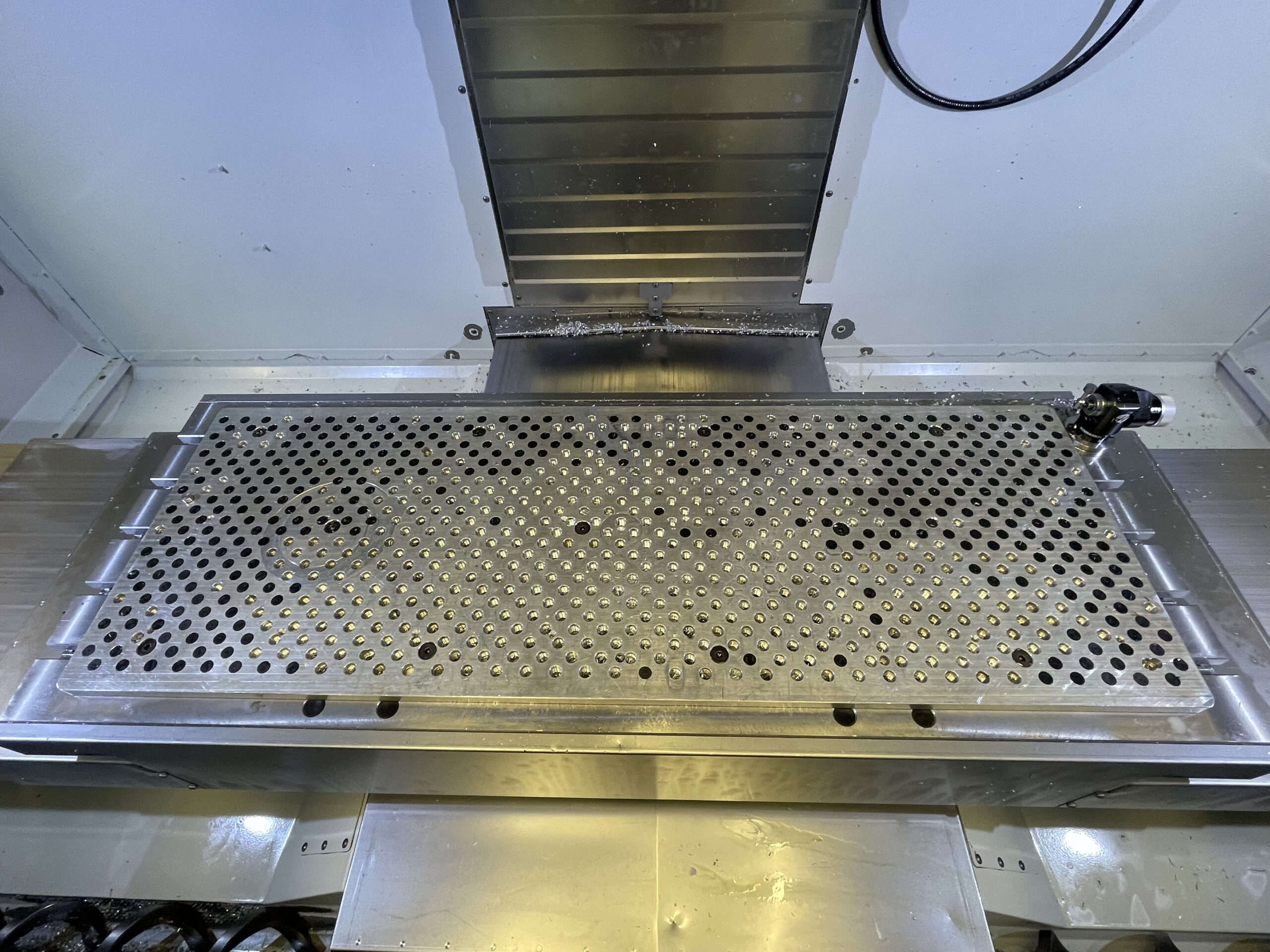 | An aluminum plate with a pattern of threaded holes in it on the VF4 plate mill. | The entire table area is usable. | ||
Toe Clamp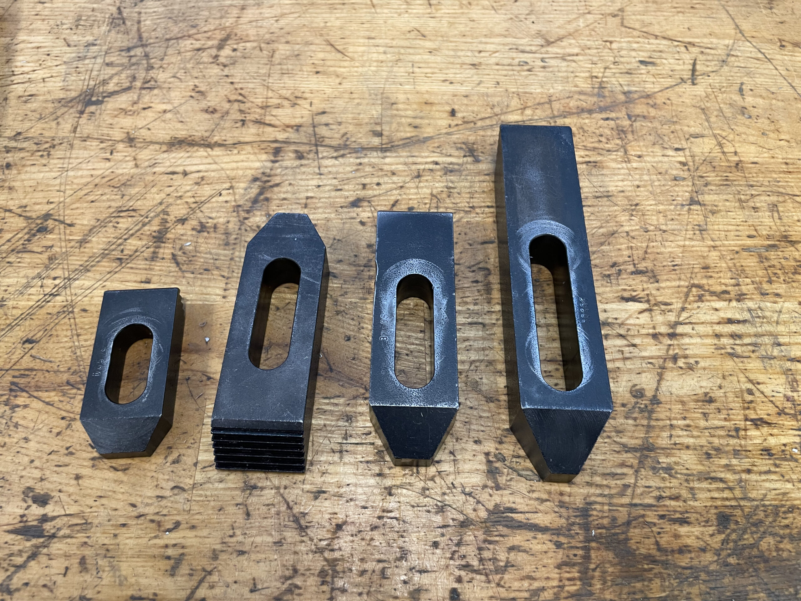 | Clamp downward onto the part via “toes” and threaded rods that go into the fixture plate. | Model toe clamps in CAM and ensure the machine does not crash with the clamps. |  | |
Snap Toe Clamp | Once attached to the fixture plate, a set of teeth can extend outward to clamp onto the part from the sides. | Model clamps in CAM and ensure the machine does not crash with the clamps. | 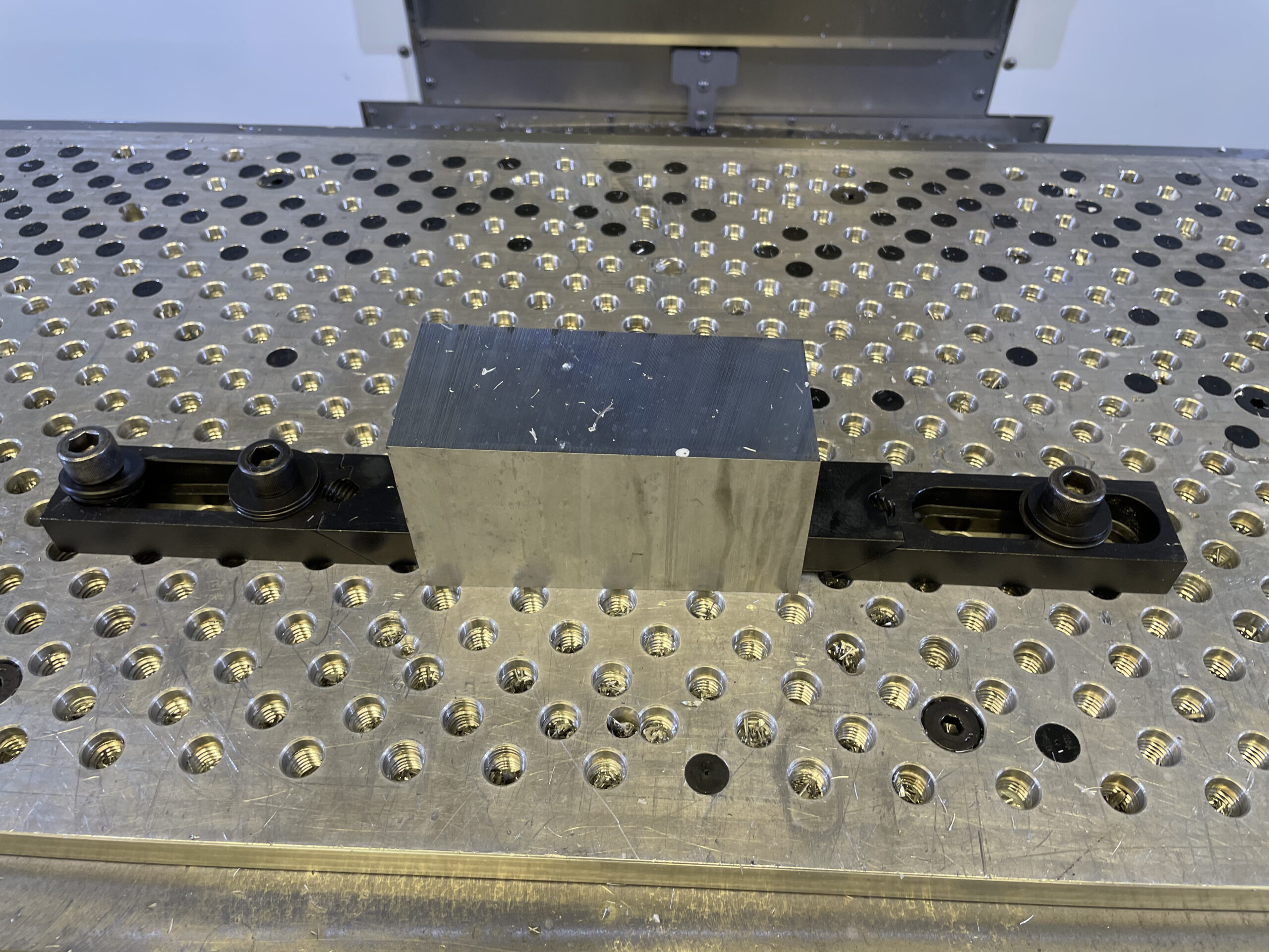 | |
Mitee Bite | A nut with an offset-headed bolt that moves side-to-side as the bolt is rotated. | Usually used for small parts where clamping force can damage part, and high-production rate parts. Requires custom fixturing. | ||
Square Collet Block | A square block to be put in the flat jaws that a 5C collet goes into | Clamps onto round stock from the OD. Maximum OD clamp of ~1″. This should ideally be put in a Kurt vice for maximum clamping area. |   |
Workholding for CNC Lathes
| Chuck | Description | Constraints | How it Clamps |
LMC 3-Jaw 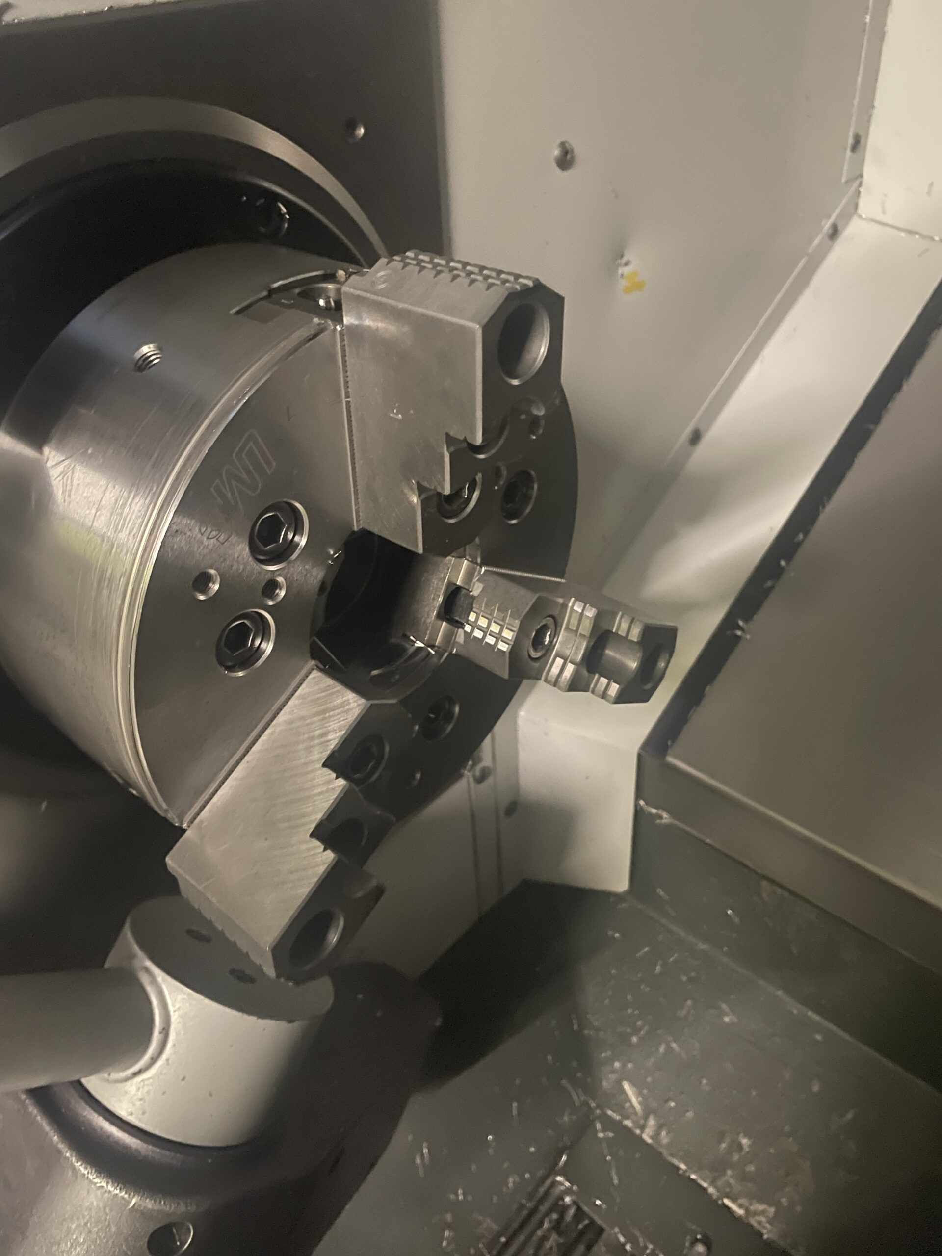 | A 3-jaw clamp for the lathe. | Maximum stock diamater of ~8″ for OD clamping. Minimum ID clamp diameter of 2″. |  |
Hex Collet Block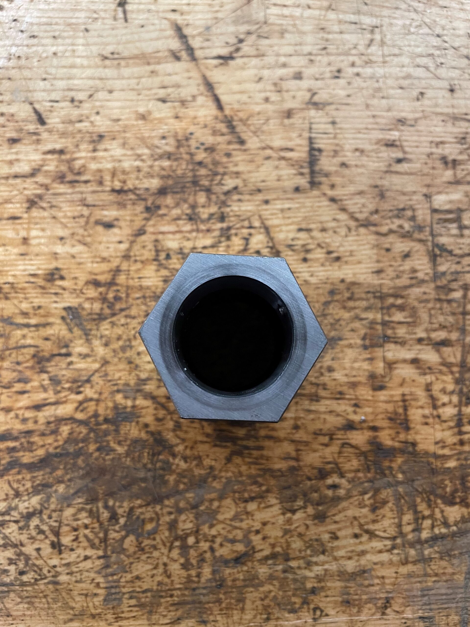 | A hex block that a 5C collet goes into. | Clamps onto round stock from the OD. Maximum OD clamp of ~1″. | 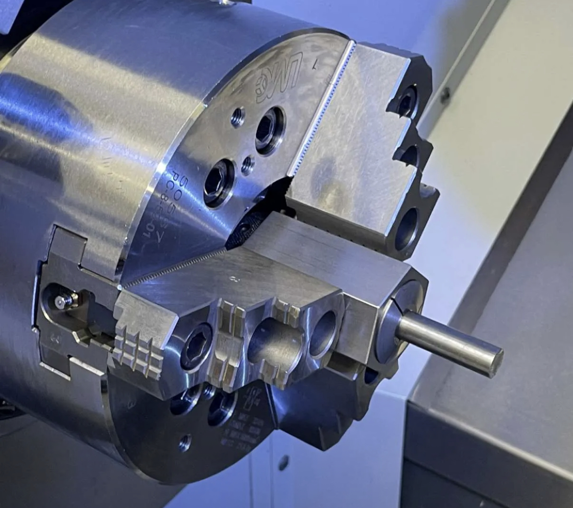 |
Parallel Heights
There are two sets of parallels, the “standard” parallels and the “thin parallels.” The standard parallels have a thickness of 0.25″ and the thin parallels have a thickness of ~0.031.” You have a greater choice of heights when using the thin parallels, whereas the standard parallels are a bit easier to set up. The parallel heights are listed below.
Standard: 1″, 1.25″, 1.5″
Thin: 0.5″, 0.625″, 0.75″, 0.875″, 1″, 1.125″, 1.25″, 1.375″, 1.5″, 1.625″
