- Tooling Note: Tools are organized by machine compatibility
- Cutting Presets: Each tool has all materials it can cut organized into categories
- N – Nonferrous, P – Steel, M – Stainless Steel, S – Superalloys, H – Hardened Materials
- See Material ISO grades to identify your material (anything from the stock room is usually aluminum N2 or mild steel P0)
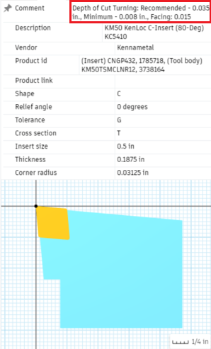
- Depths of Cut are in the comments of each tool and vary by operation! (see below)
- Facing
- Tool: any OD Turning tool (80-deg diamond preferred)
- Geometry: Model Front, any desired offset
- Passes: Enable [Multiple Passes] and [Calculate Number of Stepovers]
- Check the {Comment} within the tool selection and change the [Stepover] to the Facing Value
- Profile Roughing
- Tool: any OD or ID Turning tool (ID turning tools need an existing hole, see Drilling below)
- If ID Turning, change [Mode] to [Inside Profiling]
- Under Feed & Speed, enable [Use Constant Surface Speed]
- Geometry: If you are parting off: [Back] – [Model Back], add a small negative offset
- Passes: Set [Direction] = [Front to Back]
- Left Handed tools for back-turning use [Back to Front] direction
- If you are using a Grooving operation to reach deeper features (see below), [Grooving] = [Don’t allow grooving]
- Enable [Stock to Leave] and set [X Stock to Leave] to the minimum depth of cut, set [Z stock to leave] to the facing depth of cut
- Tool: any OD or ID Turning tool (ID turning tools need an existing hole, see Drilling below)
- Profile Finishing – after roughing!
- Tool: any OD or ID Turning tool (30-deg diamond preferred)
- If ID Turning, change [Mode] to [Inside Profiling]
- For finer results, lower [Feed Per Revolution] to 50 or 75% of the default value
- Under Feed & Speed, Enable[Use Constant Surface Speed]
- Passes: Set [Direction] = [Front to Back]
- Left Handed tools for back-turning use [Back to Front] direction
- [Linking] usually throws a warning, to solve this, under [Lead-Out] disable[Same as Lead-In] and/or increase the [Linear Lead-Out Angle] to [90 degrees]
- Tool: any OD or ID Turning tool (30-deg diamond preferred)
- Grooving
- Tool: largest grooving bar for your desired geometry
- Talk to a Peer Mentor for inside grooving operations, they’re tricky
- Under Feed & Speed, enable [Use Constant Surface Speed]
- Geometry: Offset the [Front] and [Back] containment planes to focus only on the grooves you want to cut
- Enabling Rest Machining may reduce cycle time
- Passes: [Up/Down Direction] = [Only Down]
- Enable [Roughing Passes] and ensure [Maximum Roughing Stepover] is 80% of the tool width
- Tool: largest grooving bar for your desired geometry
- Part Off
- Tool: Part off blade (or grooving bar) with enough reach
- If there is no tool with enough reach, cut a groove and follow it on the vertical bandsaw
- Under Feed & Speed, enable [Use Constant Surface Speed]
- Geometry: Enable [Edge Break] and set [Chamfer Width] to a desired value
- If you are going to flip the part and cut the other side, add a negative offset from Model Back
- Radii: Set the [Distance to Cut Below Inner Radius] to [0.05]
- Passes: Enable [Use Reduced Speed and Feed], set the corresponding radius to [0.25 in], ensure the corresponding feed rate is 25% of the normal feed rate
- Enable [Allow Rapid Retract]
- Tool: Part off blade (or grooving bar) with enough reach
- Drilling
- Tool: Drill of the desired diameter, shortest length possible for hole depth
- Additional Sizes available at Bechtel Center
- Maximum RPM of the Lathe is 4,000 drill RPM should not exceed that, recalculate Speeds and Feeds if necessary
- Geometry – Hole Faces, select hole to be drilled
- For Thru Holes: Heights – Bottom Height – [Drill Tip Through Bottom], add a small Offset
- NOTE: IF THE HOLE IS COUNTERBORED, YOU MUST SELECT THE TOP OF THE PART: Heights: [Top Height] – [Model Top]
- Tool: Drill of the desired diameter, shortest length possible for hole depth
Example Info in Tool Comment: