Definitions
CNC: Computer Numerical Control, refers to machines that are pre-programmed and controlled by computers, rather than manual control
CAM: Computer-Aided Manufacturing, the software that allows you to program toolpaths that control CNC machines. BIDC uses Fusion 360 for creating CAM.
Toolpath: A pre-calculated path a tool will take to cut out a particular geometry.
Speed: How fast the tool spins in RPM (think S for Spin).

Feed: How fast the tool moves linearly across the table in in/min (think F for Forward).
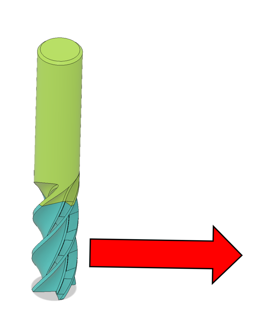
Stepover: How much a tool cuts sideways in a single cutting pass.
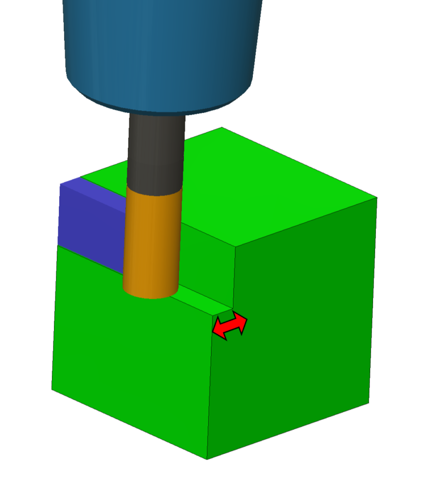
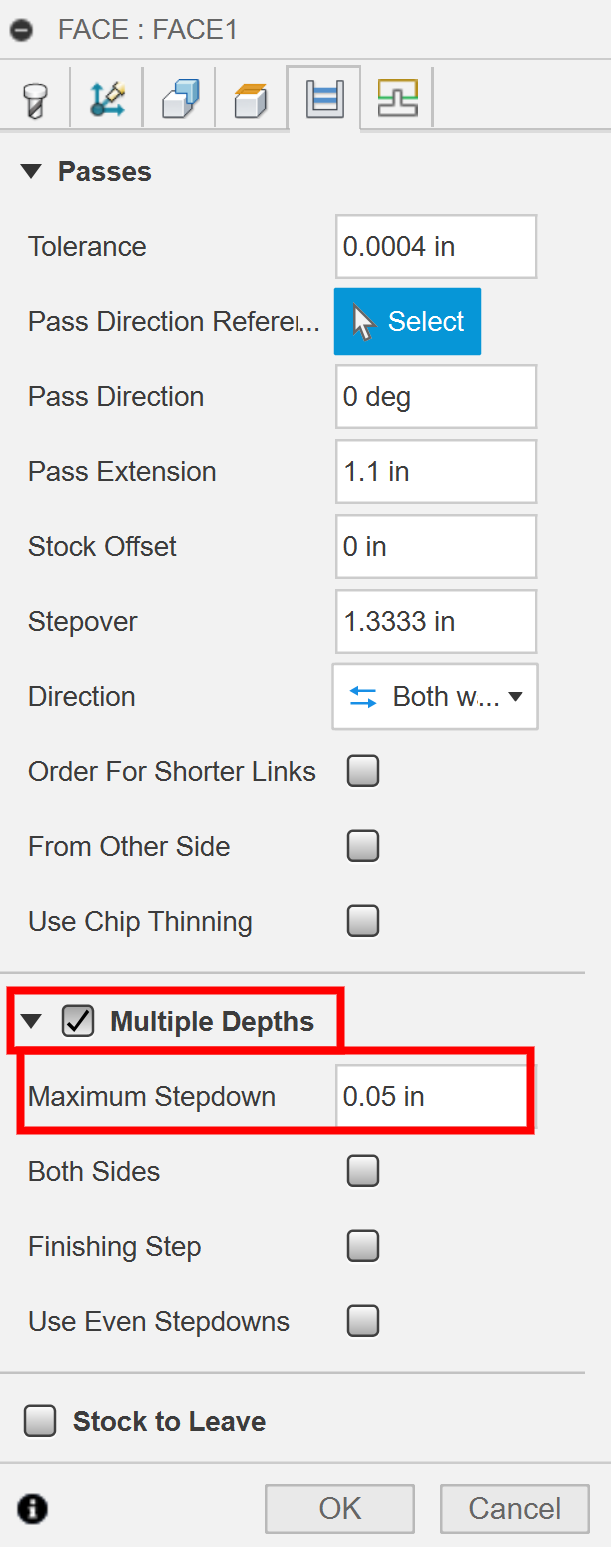
Stepdown: How deep the tool cuts in a single cutting pass.
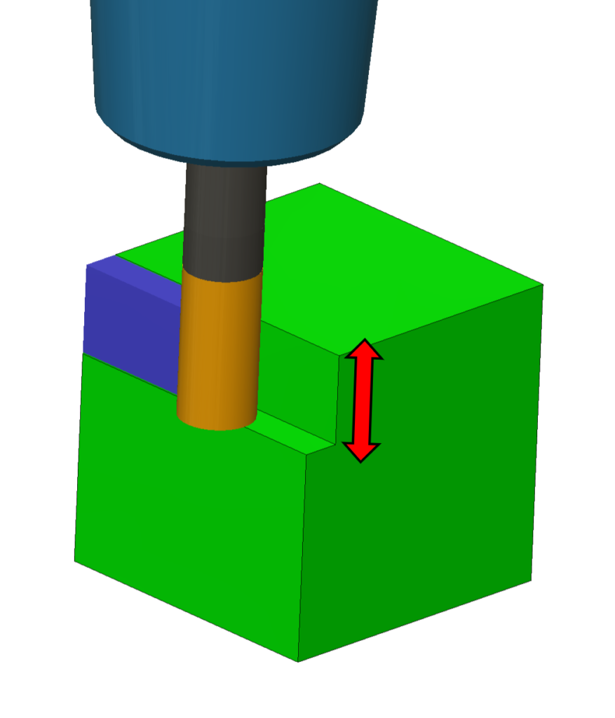
Stock: The raw block of material you will make your part out of.
Cutting Presets: Each tool has all materials it can cut organized into categories
- N – Nonferrous, P – Steel, M – Stainless Steel, S – Superalloys, H – Hardened Materials
- See Material ISO grades to identify your material (anything from the stock room is usually aluminum N2 or mild steel P0)
Minor Notes
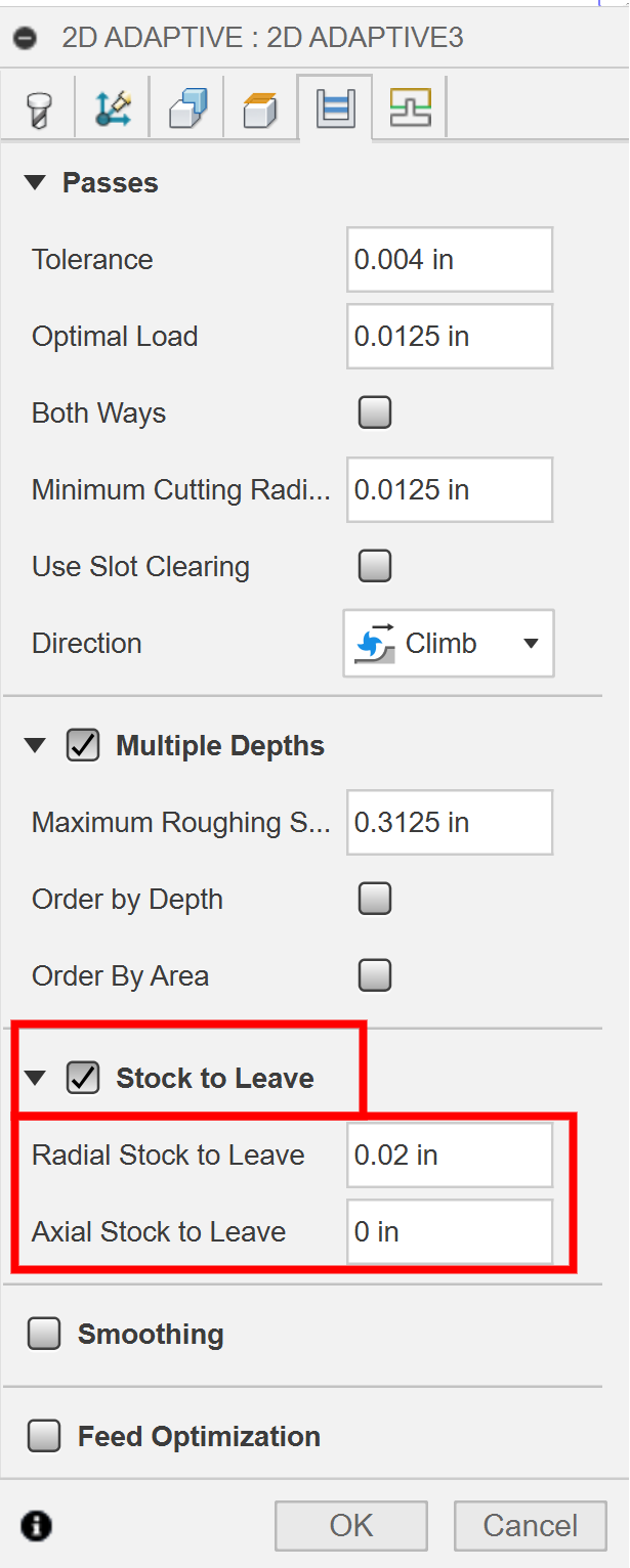
You can set many of the settings for each toolpath to be dependent on Expressions, which will adapt based on the selected tool’s parameters. You can click on the 3 vertical dots next to a parameter and click [Edit Expression] to type in parameters like tool_stepover and tool_stepdown for values like Stepover/Optimal Load and Stepdown, respectively. Then save as user default
Each tool has its speeds and feeds precalculated for you. We use the Kennametal Novo Tool to determine these speeds and feeds. Feel free to explore this and ask a TA for more information.
Probing
The CNC Mill first needs to figure out where your stock is located on the machine. We typically cannot place stock in the machine exactly where it is within CAM (to within 0.001″) by hand. So, probing will almost always be the first toolpath in your setup. The probe will physically make contact with your part to find certain surfaces. If the probe touches two parallel surfaces, it will find the center point between them. We can also probe later in the operation to get better accuracy or determine deviations from expected part geometry. The probe tool itself is loaded in every CNC Mill in tool slot #20.
When it comes to what to probe, usually you probe off your stock on the first operation, and off the machined surfaces of your part/the vice for subsequent operations. As said before, stock usually isn’t very square. If you probe off the stock on the second operation, there is a chance your features from op2 won’t be aligned with those from op1. So, you want to probe off trusted surfaces. If your part’s machined surfaces are resting flat in a vice, then you can trust that probing off of the vice (most commonly in the z-axis) will ensure your toolpaths will align with where your part actually is. Just think about what is being probed, and how that locates where the machine will run the toolpaths.
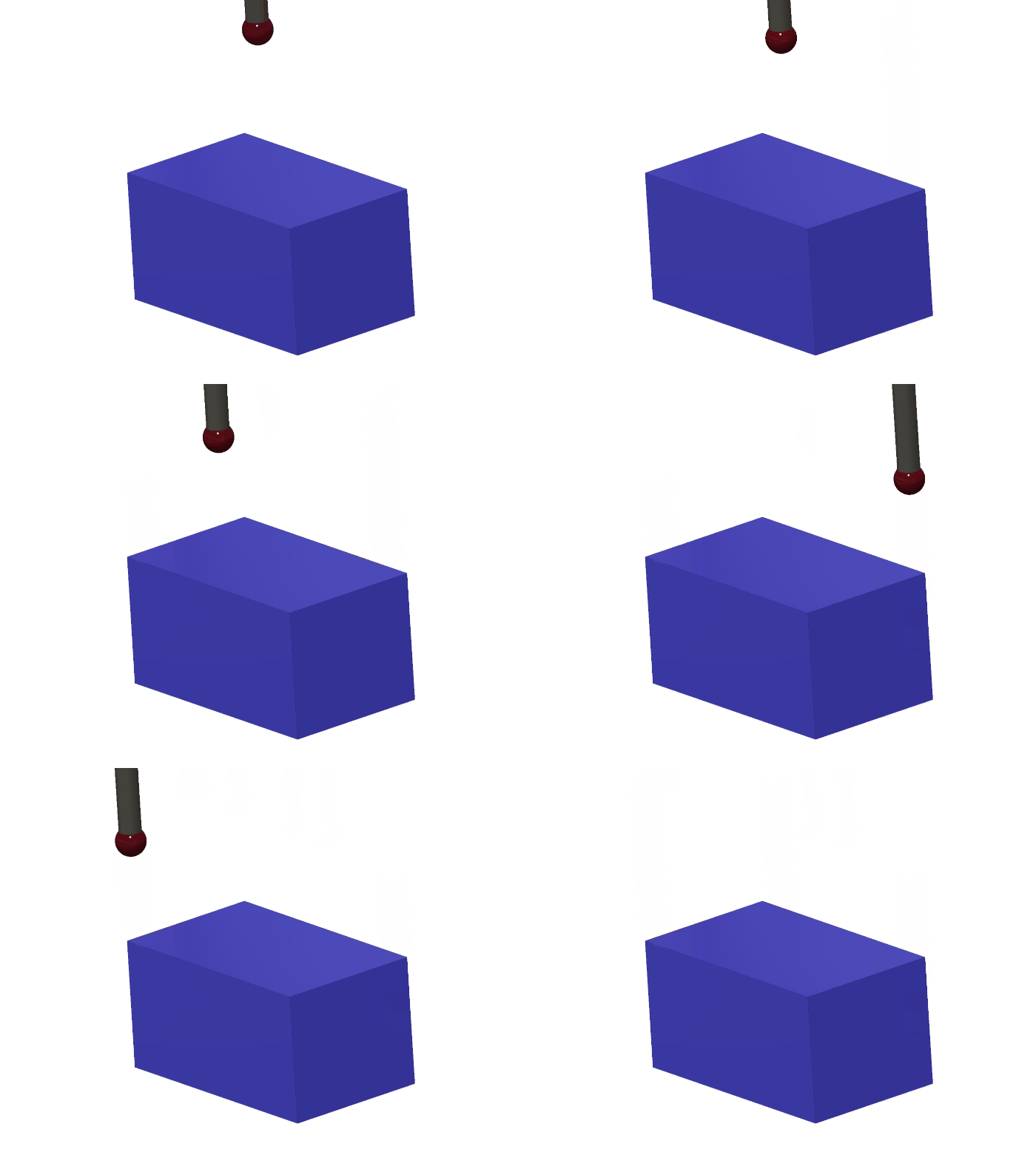
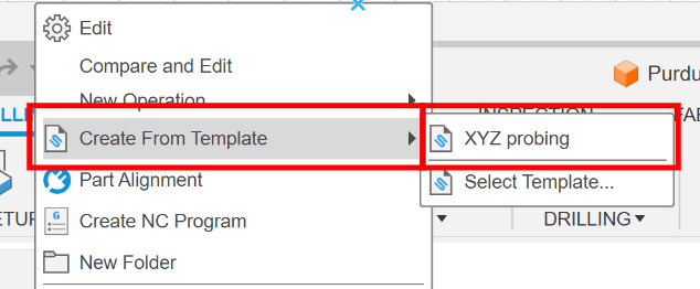
To create your probe toolpath, use the probing template! Right-click on your setup, select “Create from Template”, then “Select Template”, and click on “XYZ Probing.” This will automatically generate two named toolpaths (one for Z-probing and one for XY-probing) with the correct settings, so all you need to do is select the geometry you want to probe. If the template is missing from the cloud and the probing toolpath must be made manually, the following settings are what you need to set.
Probe WCS Settings
- Tool: Work Probe
- Lead-In Feedrate can be increased to a maximum of 100in/min, 50 is recommended
- Geometry: whatever surfaces you would like to reference, you can select the top surface and change it to probe XY or probe Z surface, or select vertical surfaces directly (ask if you’re not sure)
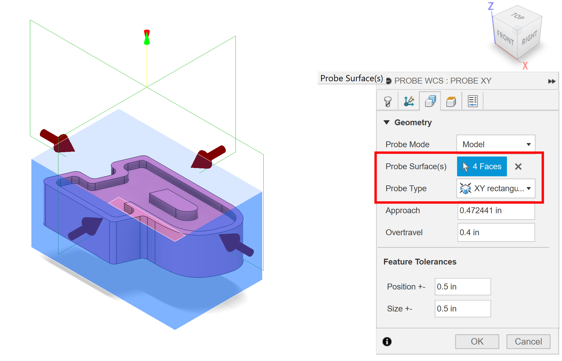
- Heights: Change the bottom height to [From Probing Surface Top] and adjust the offset to make sure the ball of the probe tip makes full contact with the probing surface (-0.125in works well)

- Actions: Check [Override Driving WCS] and change the WCS Offset to 2

- Repeat for additional axes
2D Operations
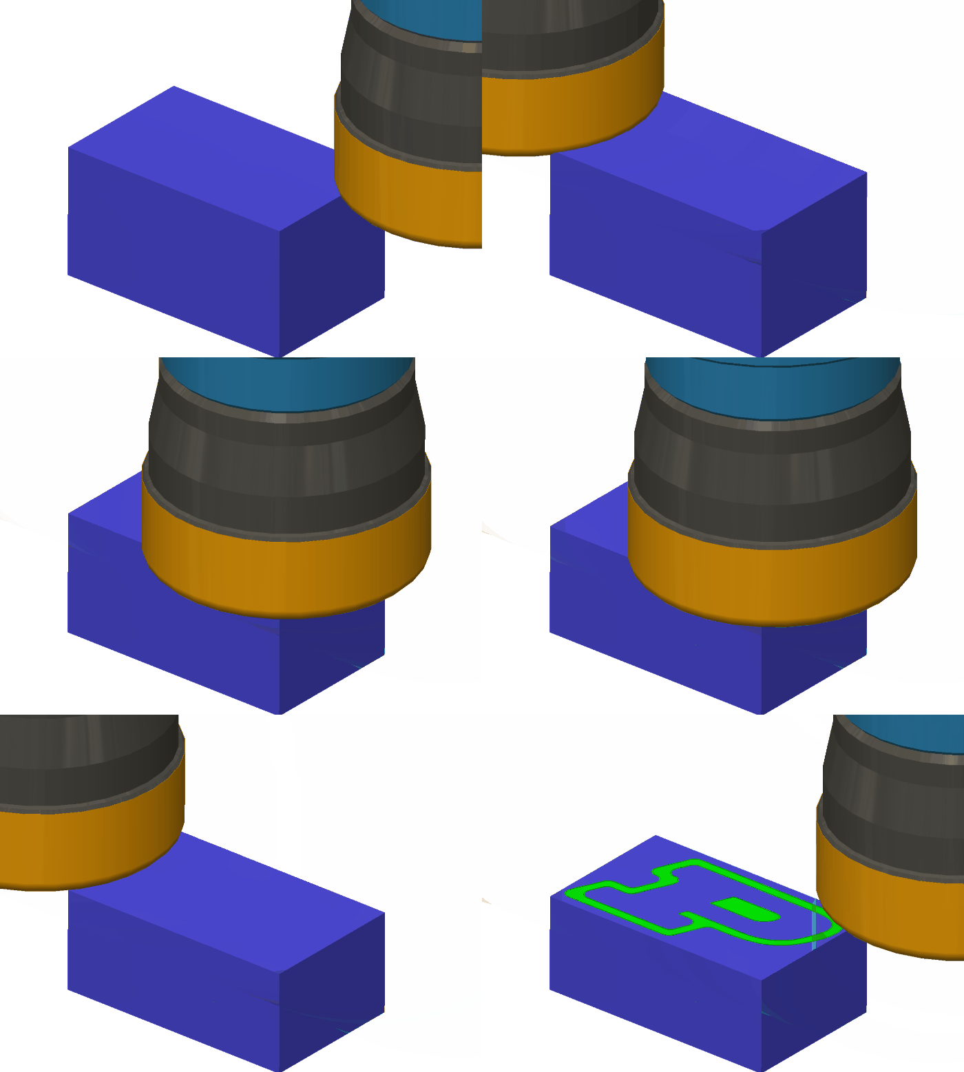
The 2D set of toolpaths in Fusion 360 are the most basic but often used toolpaths. In most case, most if not all of your toolpaths will be from the 2D section.


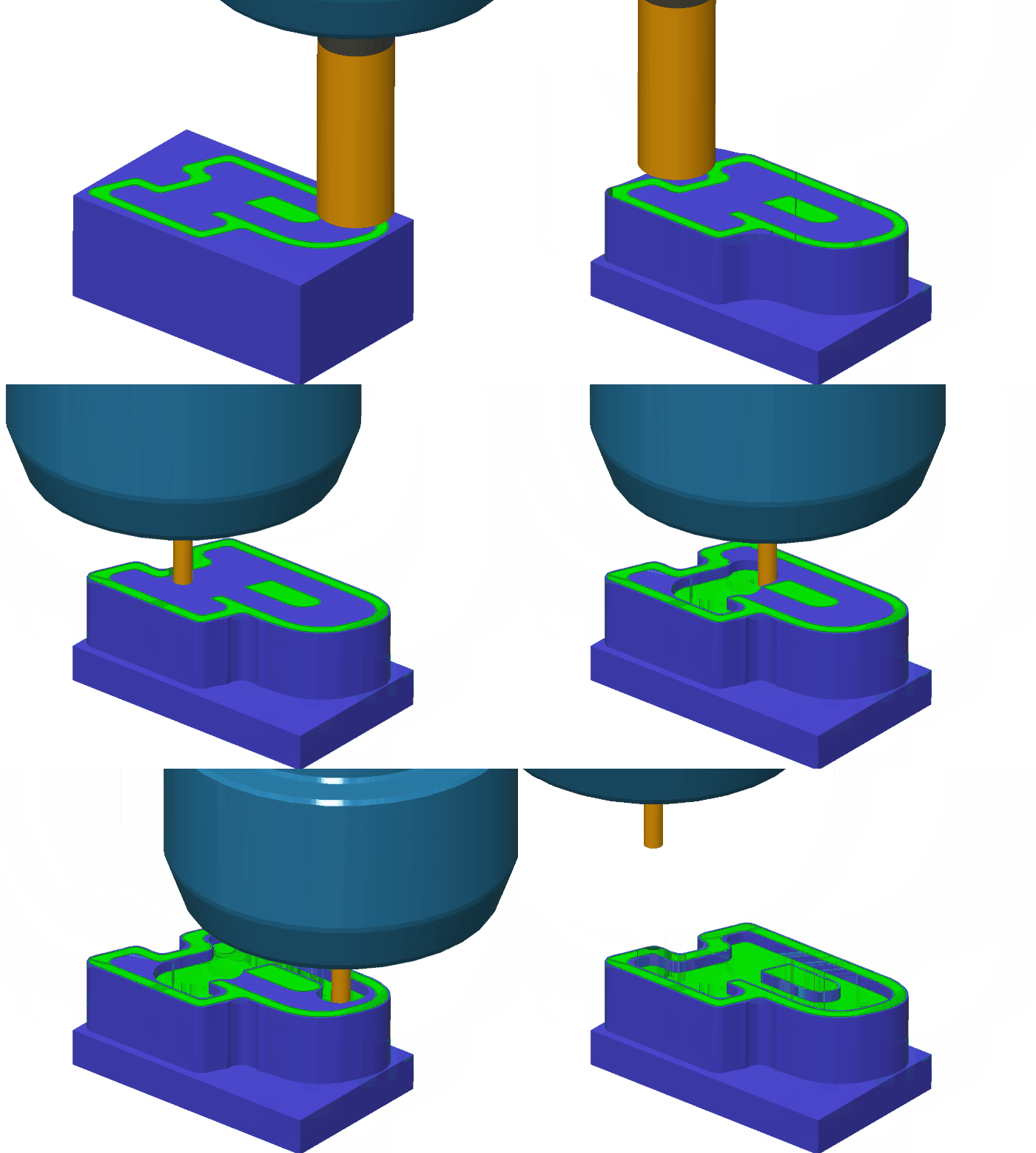

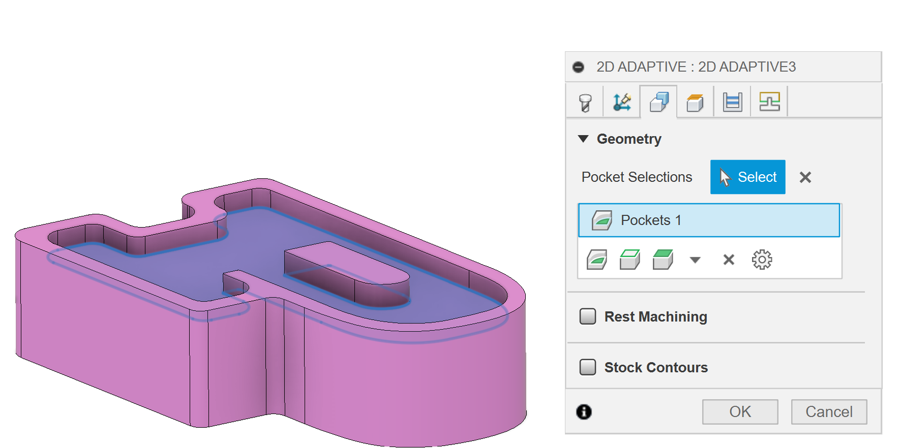
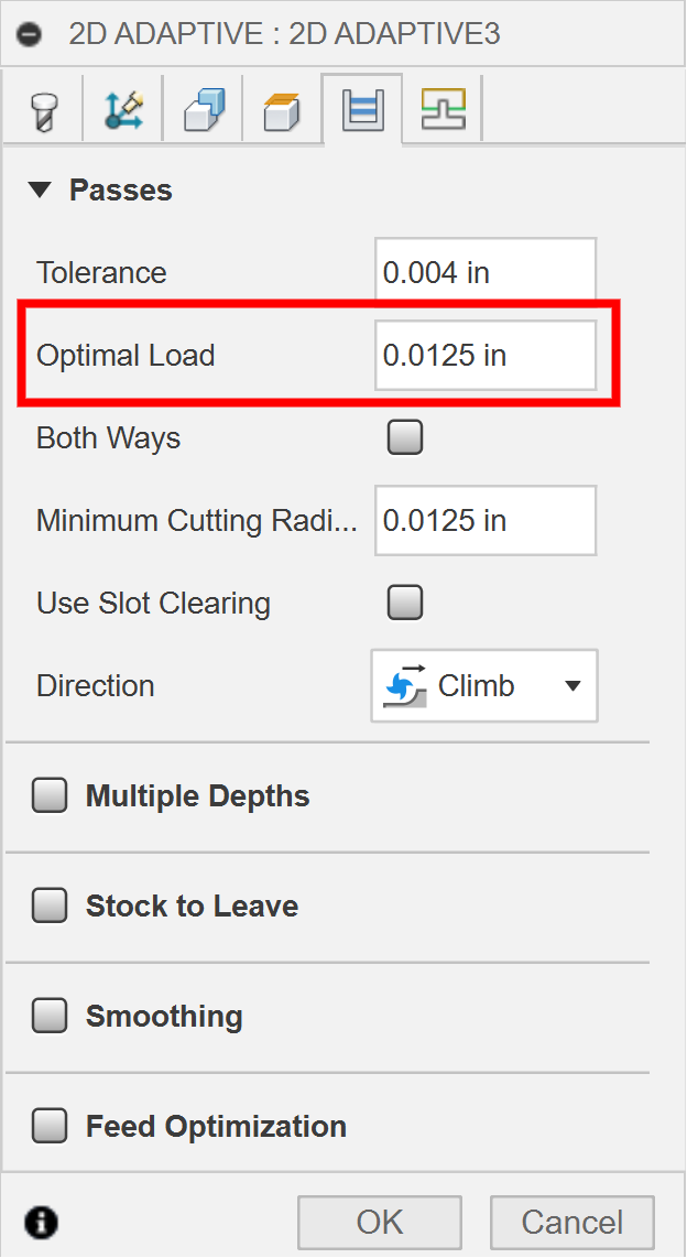
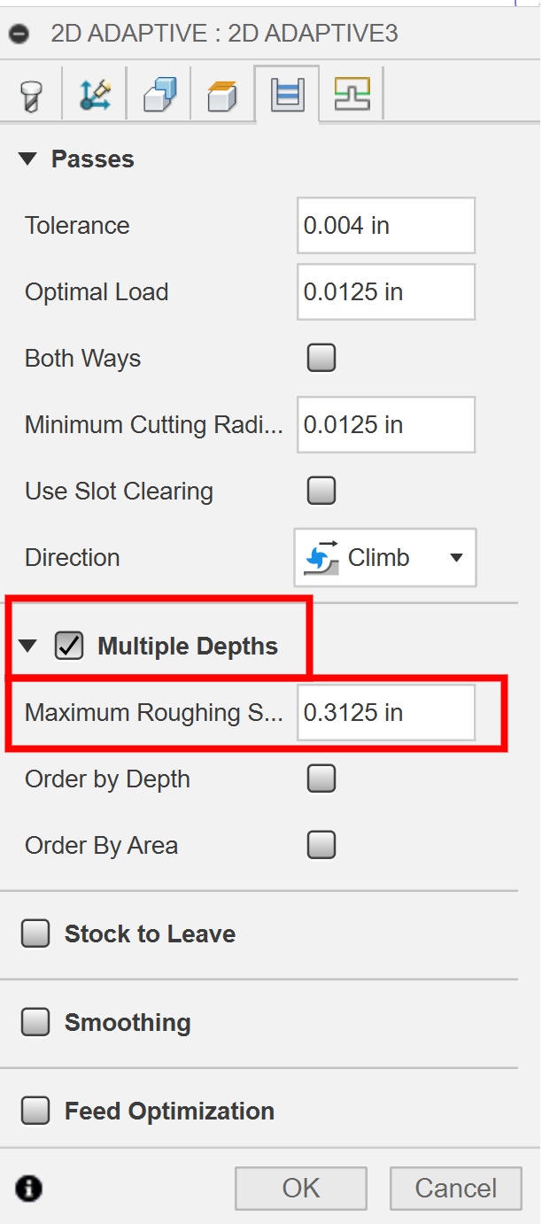

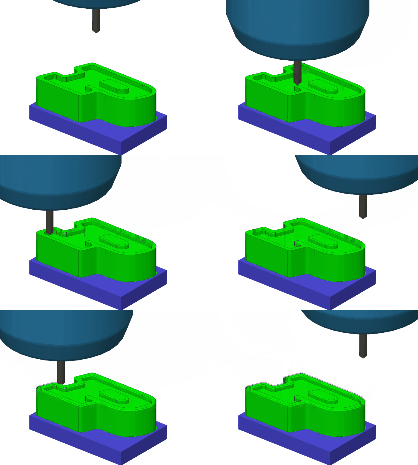
Drilling
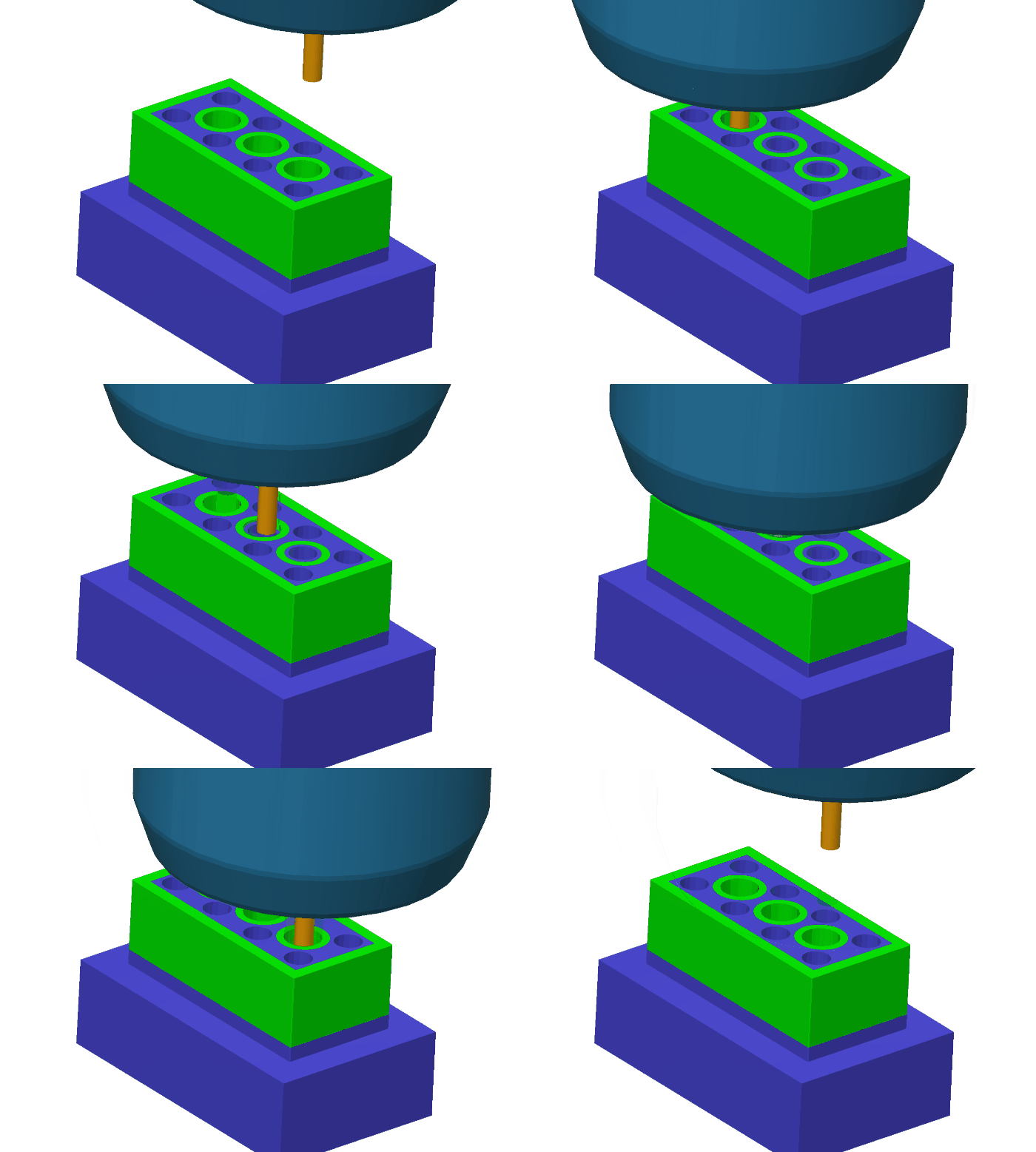
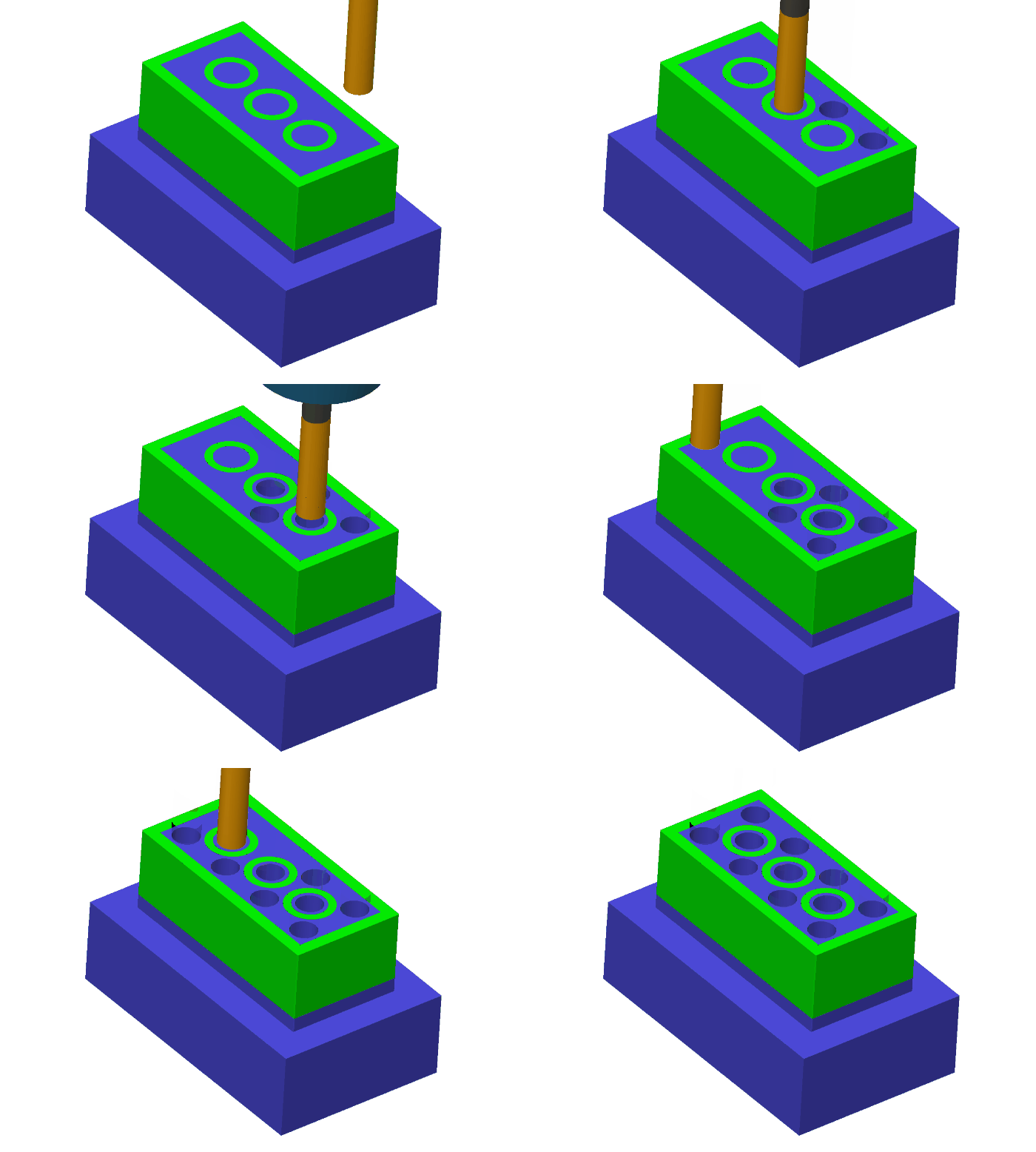
Drilling is used to make holes. While you can bore out hole sizes with an endmill, it is much easier and faster to use a drill to make the hole. So, try to size your holes to fit to those in our drill library! Know your tool material for drills. If using a carbide drill, you need a flat surface. A carbide drill cannot do any form of pecking, so it must go straight down to the bottom of the hole without stopping. Use Through-Spindle Coolant if the machine supports it. You cannot use a carbide drill for creating a counterbore, or if two holes meet each other. If using HSS, you will need to create a dimple/spot hole for the drill to guide it in. You can use a spot drill or a carbide drill for this. You also need to set the drill type to a pecking of some sort. For larger-size HSS drills, drilling out the hole completely with a smaller-size drill is also advisable.
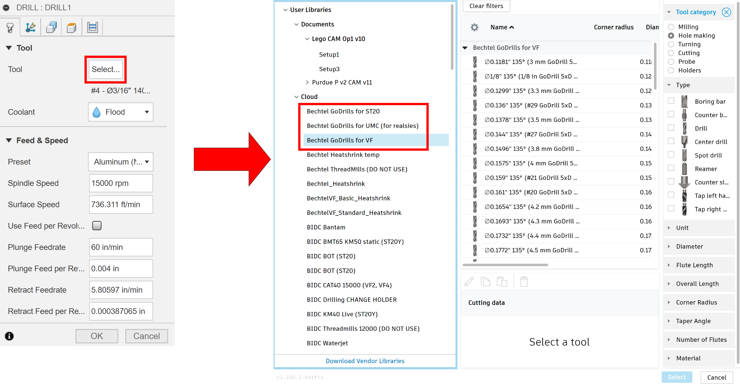
Drill Settings
- Tool: Drill of the desired diameter, shortest length possible for hole depth
- Geometry – Hole Faces, select holes to be drilled, use [Select Same Diameter] for repeated holes

- For Thru Holes: Heights – Bottom Height – [Drill Tip Through Bottom], add a small Offset
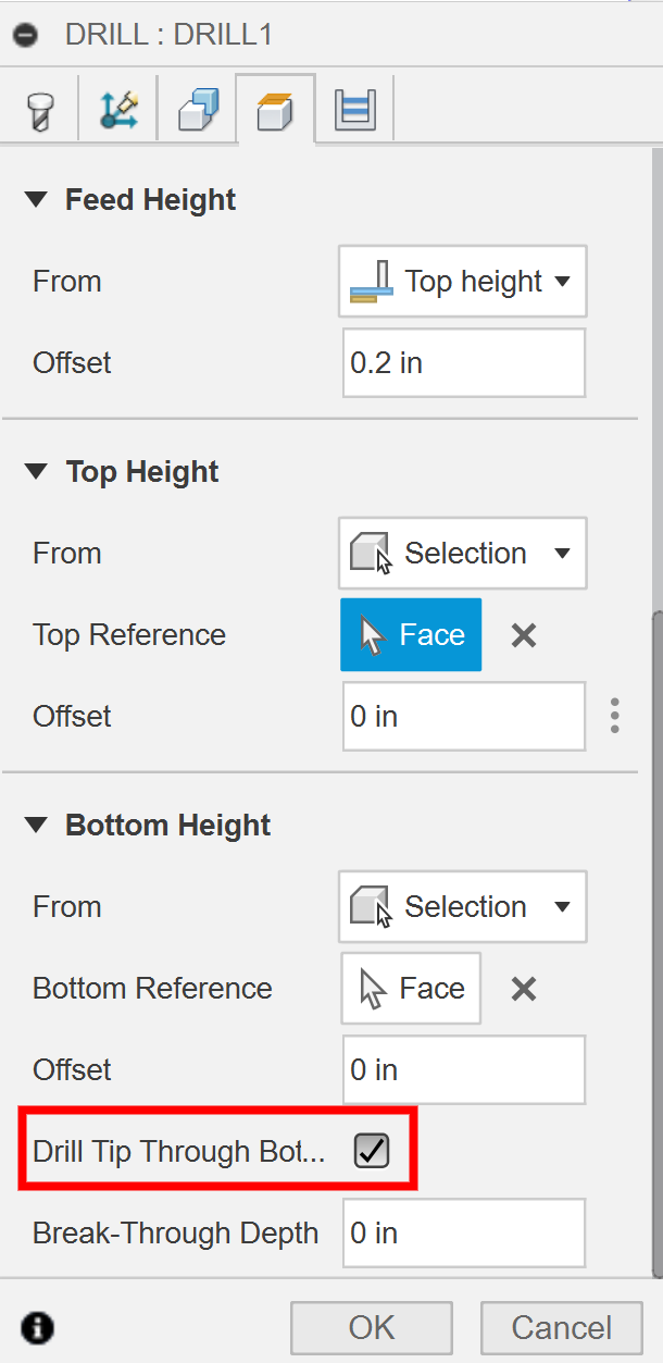
- NOTE: IF THE HOLE IS COUNTERBORED, YOU MUST SELECT THE TOP OF THE PART: Heights: [Top Height] – [Model Top]
- Cycle – Cycle Type [Drilling – rapid out] for carbide drills (GoDrills) or [chip breaking – partial retract]/[deep drilling – full retract] for HSS drills.

3D Operations
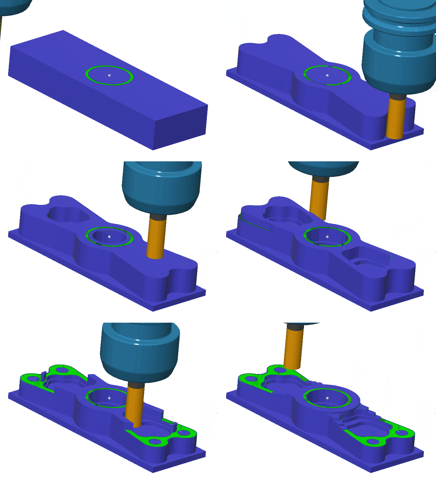
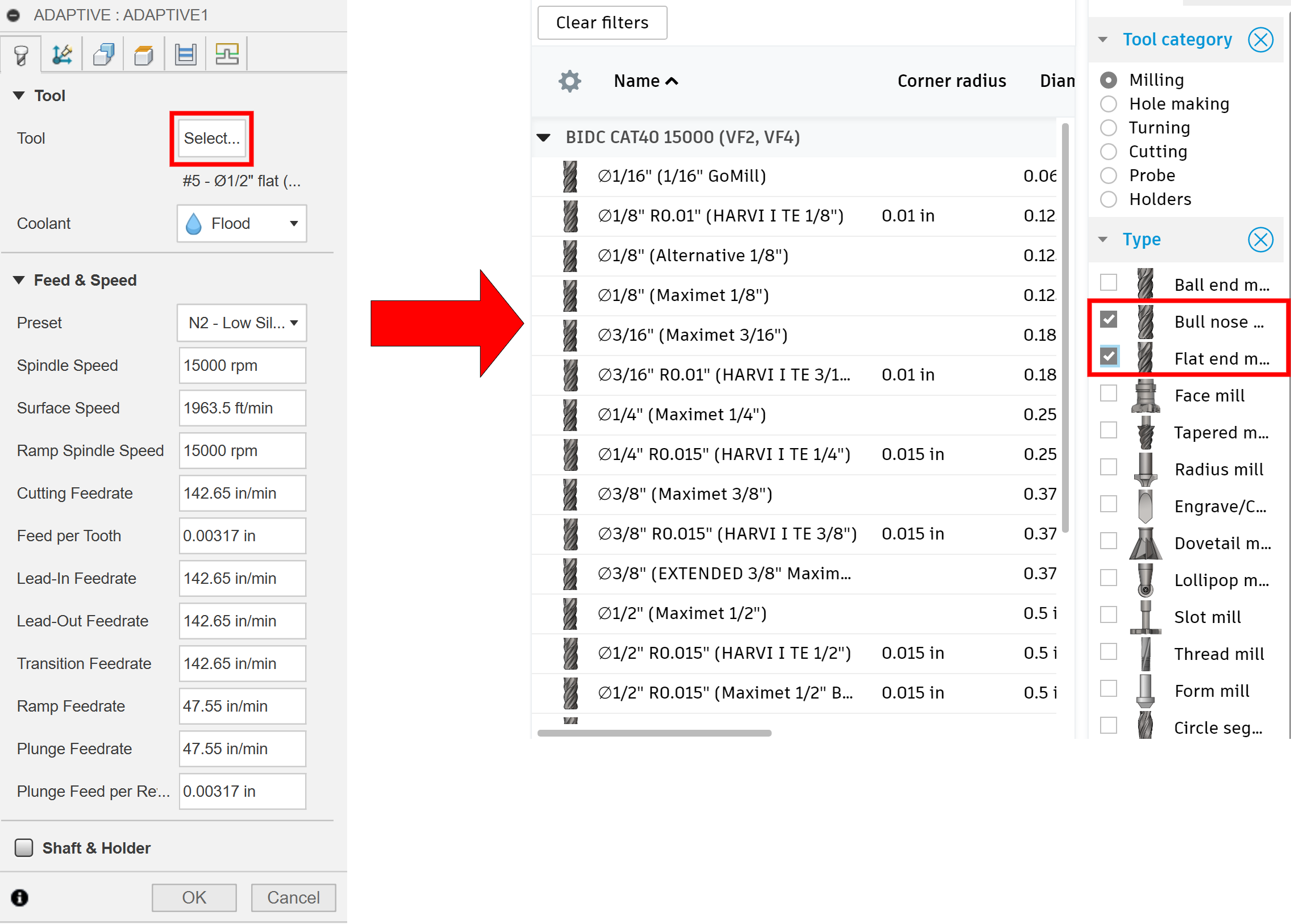
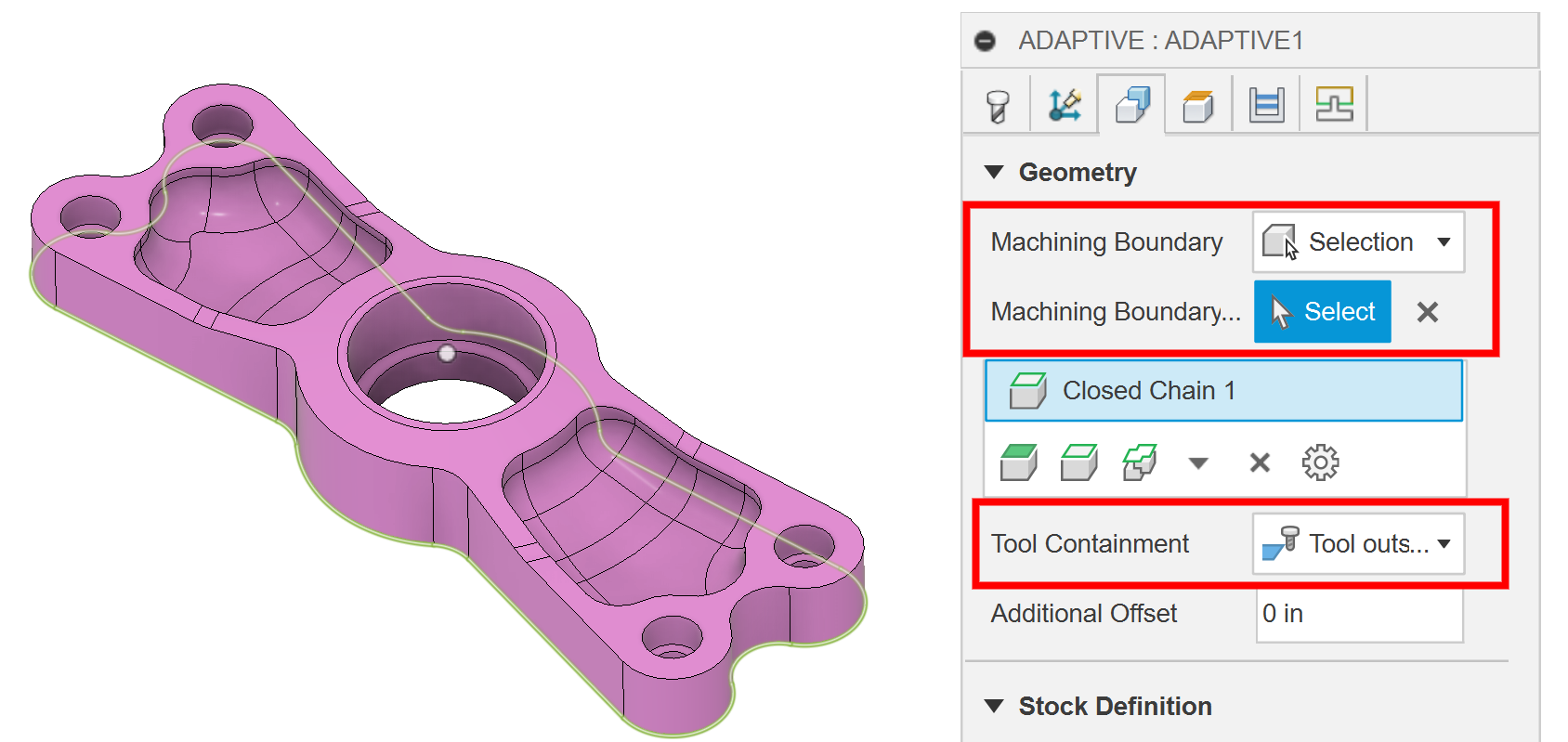
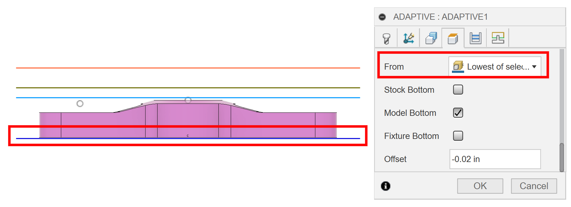


Multi Axis Operations
There are a couple of multi-axis toolpaths within Fusion 360 for use on the 5-axis. For some of the 3D finishing operations, you will have the ability to turn those into multi-axis toolpaths. There are also some dedicated multi-axis toolpaths. Ask a BIDC Metal Shop TA for more help in setting up 5-axis operations.
Further Toolpaths
Fusion 360 has many more toolpaths than what was covered here! These just represent the most common ones. If you want to learn more about a particular toolpath, all you need to do is hover your mouse over the toolpath, and a window will pop up explaining how it works.
Troubleshooting
- Review the simulation to check for any crashes
- Warning that a height was raised or a lead in/out was modified: Not a problem
- Rapid Collision with Stock: Check heights and selected geometry
- If the toolpath not doing what you want it to: Try another toolpath or mess around in Passes
Note: this is a simulation that can do unrealistic things with tools that will break them, so being more conservative with your toolpaths is best.