Homework H6.C – Sp 25

Problem statement
Solution video


DISCUSSION THREAD

Ask your questions here. Or, answer questions of others here. Either way, you can learn.


DISCUSSION and HINTS
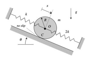
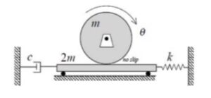
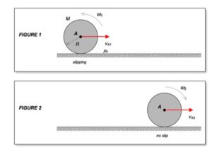
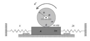
As the system moves, there is no slipping between the contact point C on the drum and block A.  This represents a constraint between the drum rotation and the block translation. We will deal with this in Step 3 of the derivation of the equation of motion below.

Recall the following four-step plan outline in the lecture book and discussed in lecture:

Step 1: FBDs
Draw individual free body diagrams (FBDs) of the drum and the disk. Be sure to include the equal-and-opposite contact forces on both the drum and the block. It is important to temporarily define a coordinate that describes the motion of the block. Let’s call that variable “x“, and define it to be positive to the right. With this definition, the spring forces on the left and right side of the block are kx and 2kx, respectively, with both forces pointing to the left.

Step 2: Kinetics (Newton/Euler)
Using your FBDs from above, write down the Euler equation for the drum, and the Newton equation for the block. Combine these two equations through the elimination of the drum-to-block contact force.

Step 3: Kinematics
You need to relate the angular acceleration of the drum to the acceleration of the block. How is this done? What are the results? Also, how do you relate the stretch/compression x in the two springs in terms of θ?

Step 4: EOM
From your equations in Steps 2 and 3, derive the equation of motion (EOM) of the system in terms of θ.

Once you have determined the EOM for the system, identify the natural frequency from the EOM. Also from the EOM, we know that the general form of the response is: θ(t) = C*cos(ωnt)+ S*sin(ωnt). How do you find the response coefficients C and S?

Homework H6.D – Sp 25

Problem statement
Solution video

DISCUSSION THREAD

Ask your questions here. Or, answer questions of others here. Either way, you can learn.


DISCUSSION and HINTS

Recall the following four-step plan outline in the lecture book and discussed in lecture:

Step 1: FBDs
Draw individual free body diagrams (FBDs) of the two disks and block A.  Note that the tension forces in the different sections of the cable are NOT equal. It is important to temporarily define coordinates that describe the rotations of the two disks. Let’s call these θC and θO,  and define these to be positive in the clockwise sense.

Step 2: Kinetics (Newton/Euler)
Using your FBDs from above, write down the Euler equations for the two disks, and the Newton equation for the block. Combine these three equations into a single equation through the elimination of the tension forces for the equations.

Step 3: Kinematics
You need to relate the angular acceleration of the disks and the acceleration of the block. How is this done? What are the results?

Step 4: EOM
From your equations in Steps 2 and 3, derive the equation of motion (EOM) of the system in terms of x.

Once you have determined the EOM for the system, identify the natural frequency from the EOM. Note that the static deformation of the system is found by setting x_ddot = 0 in the EOM.

Homework H6.A – Sp 25

Problem statement
Solution video


DISCUSSION THREAD

Ask your questions here. Or, answer questions of others here. Either way, you can learn.


DISCUSSION and HINTS

The animation below shows the vibrational motion of this system. Take note of the relationship between the acceleration of block A and the acceleration of the disk’s center O. Note that the magnitudes of these accelerations are not the same. We will focus on this in Step 3 of deriving the equation of motion.

Recall the following four-step plan outline in the lecture book and discussed in lecture:

Step 1: FBDs
Draw individual free body diagrams (FBDs) of the disk and Block A.

Step 2: Kinetics (Newton/Euler)
Write down the Euler equation for the disk and the Newton equation for Block A. The the disk rolls without slipping, it is recommended that you write your Euler equation for the disk in terms of the no-slip contact point (let’s call that point C).

Step 3: Kinematics
Since the disk rolls without slipping at the contact point with ground (let’s call that point C), we can write:

a= aC + αdisk x rE/C – ωdiskrE/C

where E is the top point on the disk.

What is the relationship between the acceleration of point E and Block A?

Step 4: EOM
From your equations in Steps 2 and 3, derive the equation of motion (EOM) of the system in terms of x.

Homework H6.B – Sp 25

Problem statement
Solution video


DISCUSSION THREAD

Ask your questions here. Or, answer questions of others here. Either way, you can learn.


DISCUSSION and HINTS

The animation below shows the vibrational motion of this system. Take note of the relationship between the angular motion of the two gears.  Note that neither the magnitudes nor the directions of these angular accelerations are the same. We will focus on this in Step 3 of deriving the equation of motion.

Recall the following four-step plan outline in the lecture book and discussed in lecture:

Step 1: FBDs
Draw individual free body diagrams (FBDs) of the two disks. Be sure to include the equal-and-opposite contact force between the gears on each gear.

Step 2: Kinetics (Newton/Euler)
Write down the Euler equations for the two gears. Combine these two equations through the elimination of the gear-to-gear contact force.

Step 3: Kinematics
You need to relate the angular accelerations of the two gears. How is this done? What are the results? Also, how do you relate the stretch/compression in the two springs in terms of θ?

Step 4: EOM
From your equations in Steps 2 and 3, derive the equation of motion (EOM) of the system in terms of θ.

Homework H5.O – Sp 25

Problem statement
Solution video 


DISCUSSION THREAD

Discussion and hints:

Recall the following four-step plan outline in the lecture book and discussed in lecture:

Step 1: FBDs
Draw individual free body diagrams for block A and the disk on the right. It is recommended that in drawing the FBD of the disk, include both the disk and the section of wrapped cable in the FBD, as shown below. This allows to you make the interaction forces between the cable and the disk “internal”, greatly simplifying the FBDs. Also, please note that the cable tensions TB and TC are NOT the same.

Step 2: Kinetics (Newton/Euler)
Write down the Newton/Euler equations for the block and the disk using your FBDs above. Take care in choosing the reference point for your moment equation for the disk. In order to use the “short form” of Euler’s equation, this point should be either a fixed point, the body’s center of mass, or a point whose acceleration is parallel to the vector connecting that point to the center of mass of the body. For this problem, there are no fixed points. However, the latter two options will apply. You might consider using point C since its acceleration will always point toward the center of mass of the disk. If you are not confident with this, then stick with the center of mass of the disk.

Step 3: Kinematics
Put some thought into the kinematics for this problem. Note that the contact point on the disk with the cable on the right side (point C) is the instant center for the disk. (Recall that the cable does not slip on the disk. Since the cable on the right side is stationary, then so is point C on the disk.) This is apparent when you view the animation above of the system as it moves – as point C moves into contact with the cable, its velocity is zero. This will assist you in being able to relate the motions of the center of the disk to the motion of block A.

Recall that since C is the IC of the disk, it can have, at most, a component of acceleration in the x-direction. With this, you can use the kinematic analysis below to relate the acceleration of the center of mass of the disk to its angular acceleration, and to relate the accelerations of the disk center of mass of point B.

NOTE: The acceleration of A is NOT equal to the acceleration of the center of the disk. Ask questions here on the blog if this is not clear.

Step 4: Solve
Solve your equations above for the acceleration of block A.


Any questions?

Homework H5.P – Sp 25

Problem statement
Solution video

DISCUSSION THREAD

Discussion and hints:

Recall the following four-step plan outline in the lecture book and discussed in lecture:

Step 1: FBDs
Draw a single free body diagram for the system made up of the disk and rod combined.

Step 2: Kinetics (work/energy)

  • Write down the kinetic expression for the disk and rod individually, and then add those together to find the total KE for the system of your FBD. For each KE expression, recall that your reference point needs to be either the center of mass of the body, or a fixed point on the rigid body. You might consider using the no-slip, rolling contact point as your reference point for the disk.
  • Do the same for the potential energies: write down the PEs for each body individually and add together.
  • Also, based on your FBD above, which, if any force, does nonconservative work on the system in your FBD? Determine work for such a force.

Step 3: Kinematics
Note that the instant center (IC) for the disk is the no-slip contact point C. Where is the IC for rod OA at position 2? You might want to review Chapter 2 of the lecture book in finding the IC for a rigid body moving in a plane. (Carefully study either the animation above for position 2 or the freeze frame for that position below – you can actually see the IC from these!) Locating this IC is critical for you in setting up and using the kinematics for this problem.

Step 4: Solve
Solve your equations above for the velocity of point A.


Any questions?

Homework H5.M – Sp 25

Problem statement
Solution video

DISCUSSION THREAD

Ask your questions here. Or, answer questions of others here. Either way, you can learn.


DISCUSSION and HINTS

The animation below shows the impact of particle B with the bar.

Freeze-frame of motion immediately after impact.

Recall the following four-step plan outline in the lecture book and discussed in lecture:

Step 1: FBDs
Draw a single free body diagram (FBD) of the particle and bar.

Step 2: Kinetics (impulse/momentum equations)
Using your FBD above, sum moments about point A . Consider the time of the impact to be short such that there is no change in position of either the bar or B during impact. Also, consider the particle to be of small physical dimensions.

What does your moment equation above say about the angular momentum of the system about point A?

Step 3: Kinematics
What kinematics do you need to solve this problem?

Step 4: Solve
From your equations in Steps 2 and 3, solve for the angular velocity of the bar immediately after impact.

Homework H5.N – Sp 25

Problem statement
Solution video

DISCUSSION THREAD

Ask your questions here. Or, answer questions of others here. Either way, you can learn.


DISCUSSION and HINTS

The animation below shows the impact of the particle with the rigid bar. As stated in the problem statement, the particle sticks to the bar during the short impact time.

Considering the system made up of the particle and the bar, we see that there are no fixed points that are easily recognized and determining the location of the center of the mass requires some calculation. Because of this, it is advisable to consider the particle and the bar in separate FBDs in your analysis.

Recall the following four-step plan outline in the lecture book and discussed in lecture:

Step 1: FBDs
Draw individual free body diagrams (FBDs) of the particle and bar. Be sure to draw the impact force on both FBDs.

Step 2: Kinetics (impulse/momentum)
Consider the linear impulse/momentum equation for the particle and the angular and linear impulse/momentum equations for the bar. Note that each of these equations will include the impulse of the impact force.

Eliminate the impulse of the impact force from the above three equations. This will leave you with two equations in terms of the post-impact velocity of the particle, the post-impact velocity of the bar’s center of mass, and the post-impact angular velocity of the bar.

Step 3: Kinematics
Since the particle sticks to the bar during impact, you can relate the post-impact velocities above through the rigid body kinematics equation:

vB= vG + ωbar x rB/G 

where B is the top point on the bar where the particle impacts and sticks.

Step 4: Solve
From your equations in Steps 2 and 3, solve for the velocity of G and the angular velocity of the bar immediately after impact.

Homework H5.K – Sp 25

Problem statement
Solution video

DISCUSSION THREAD

Ask your questions here. Or, answer questions of others here. Either way, you can learn.


DISCUSSION and HINTS

The animation below shows the motion of the disk as it moves along the incline. Included in the video are the friction and normal forces (FF and FN) acting on the disk as it moves.

Recall the following four-step plan outline in the lecture book and discussed in lecture:

Step 1: FBDs
Draw a free body diagram (FBD) of the disk. In drawing your FBD, please note that the friction force is NOT proportional to the normal force N; that is, f ≠ μN. Why is that?

It is recommended that you choose a set of coordinates that are aligned with the ramp. For example, choose the x-direction down the incline and the y-direction   perpendicular to the ramp pointing up and to the right.

Step 2: Kinetics (Newton/Euler)

  • Based on your FBD above, write down the impulse/momentum equation in the x-direction for the disk.
  • Based on your FBD above, write down the angular impulse/momentum equation for the disk.
  • Combine the two equations above by eliminating the impulse of the friction force from the equations.

The above gives you a single equation in terms of two variables: vO and ωdisk.

Step 3: Kinematics
Note that the no-slip contact point of the disk with the incline is the instant center (IC) of the disk. Let’s call that point C. Since C is the IC of the disk, you can readily relate the angular velocity of the disk to the velocity vector of the disk center O through:

vO= vC + ωdisk x rO/C = ωdisk x rO/C

Be careful with signs.

Step 4: Solve
From your equations in Steps 2 and 3, solve for the velocity of point O on the wheel at time 2.

Homework H5.L – Sp 25

Problem statement
Solution video

DISCUSSION THREAD

Ask your questions here. Or, answer questions of others here. Either way, you can learn.


DISCUSSION and HINTS

Recall the following four-step plan outline in the lecture book and discussed in lecture:

Step 1: FBDs
Draw a free body diagram (FBD) of the disk.

Step 2: Kinetics (Newton/Euler)
Based on your FBD above, write down the linear impulse momentum and angular impulse/momentum equations for the disk.

Step 3: Kinematics
What kinematics do you need here to solve?

Step 4: Solve
From your equations in Steps 2 and 3, solve for angular velocity of the disk at time 2 and the reactions at O.