Discussion and hints:
Shown below is an animation of the results of a simulation of the motion corresponding to an UNDERDAMPED system. The response is oscillatory, however, the amplitude of the response decays away at an exponential rate.
For this problem, you are asked to determine the amount of damping (i.e., the value of c) for which the system is CRITICALLY damped (ζ = 1). The animation below shows the response of such a critically damped system. Not that with this value for the damping ratio ζ, the oscillations are damped out, with the response asymptotically approaching the steady-state static equilibrium state.
The derivation of the dynamical equation of motion (EOM) for a system is a straight-forward application of what we have learned from Chapter 5 in using the Newton-Euler equations. The goal in deriving the EOM is to end up with a single differential equation in terms of a single dependent variable that describes the motion of the system. Here in this problem, we want our EOM to be in terms of θ(t).
Recall the following four-step plan outline in the lecture book and discussed in lecture:
Step 1: FBDs
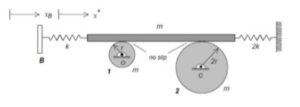
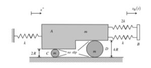
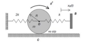
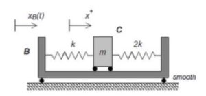
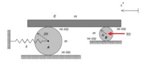
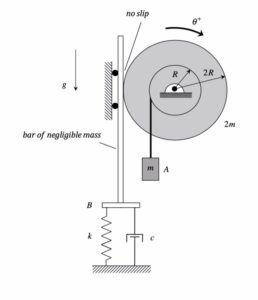
Draw individual FBDs of the drum and the bar. Define a translation coordinate, x, for the bar.
Step 2: Kinetics (Newton/Euler)
Write down the Newton/Euler equations for the drum and the bar.
Step 3: Kinematics
Use the no-slip condition between the drum and the bar to relate x to θ.
Step 4: EOM
Combine your Newton/Euler equations along with your kinematics to arrive at a single differential equation in terms of the dependent variable θ.
You will then need to find the static rotation of the disk from your EOM. Also, put the EOM in “standard form” in order to find the undamped natural frequency ωn and the damping ratio ζ of terms of the given parameters for the system. Critical damping corresponds to ζ = 1.
Any questions?