| Problem statement Solution video |
DISCUSSION THREAD
Any questions? Ask/answer questions in the discussion thread below.
DISCUSSION
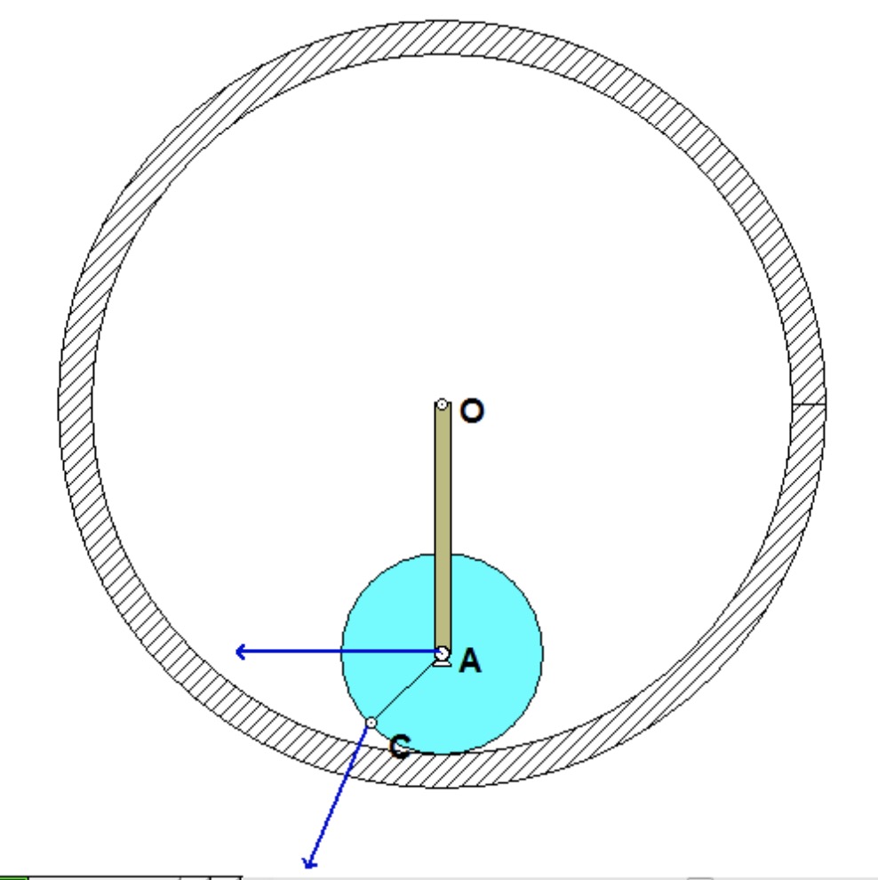
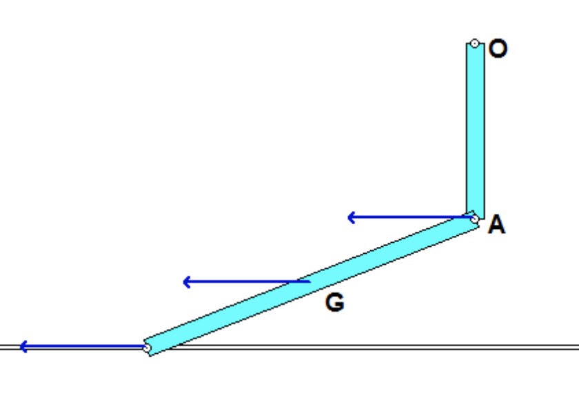
The animation below is for the case of c = 0 (undamped).
The derivation of the dynamical equation of motion (EOM) for a system is a straight-forward application of what we have learned from Chapter 5 in using the Newton-Euler equations. The goal in deriving the EOM is to end up with a single differential equation in terms of a single dependent variable that describes the motion of the system. Here in this problem, we want our EOM to be in terms of θ(t).
Recall the following four-step plan outline in the lecture book and discussed in lecture:
Step 1: FBDs
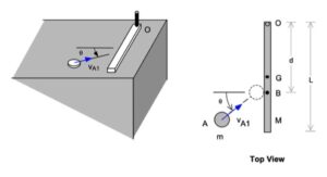
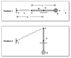
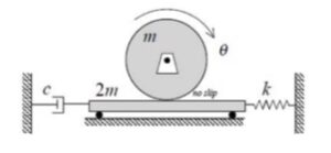
Draw individual free body diagrams for the drum and the block. Choose a translational coordinate (say x, defined as being positive to the left). Be sure the get the correct direction for the spring and dashpot forces on the block. Also, take care in drawing the friction force on the drum as being equal and opposite to the friction force on the block.
Step 2: Kinetics (Newton/Euler)
Write down the Newton/Euler equations for the drum and block based on your FBDs above. Be sure to be in consistent in your sign conventions for forces/translation and moments/rotation.
Step 3: Kinematics
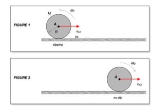
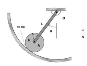
The contact point of the drum on the block (call it point A) is a no-slip point; that is, the horizontal component of acceleration of A is equal to the acceleration of the block.
Step 4: EOM
Combine your Newton/Euler equations along with your kinematics to arrive at a single differential equation in terms of the dependent variable θ.