The Electronics Lab is home to a wide variety of electrical manufacturing equipment, including soldering irons, desoldering stations, a PCB mill, a reflow oven, and every consumable necessary to build a circuit board from start to finish. Users will also find oscilloscopes, signal generators, power supplies, and multimeters to aid in testing and troubleshooting all common electrical components. We are more than happy to answer questions, and we hope to see you in the lab!
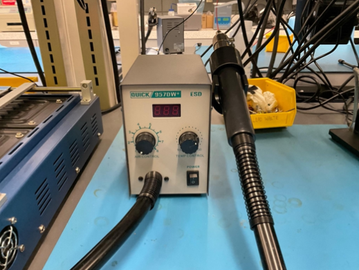
Manufacturer: Quick Model: 957DW+ Key Specs: 580W Adjustable airflow and temperature
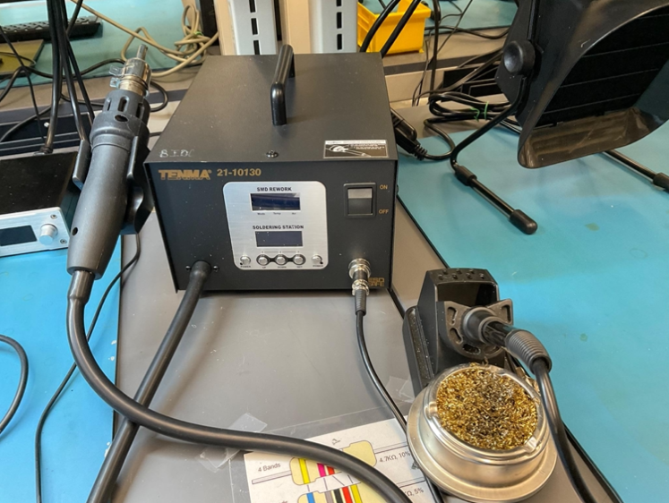
Manufacturer: Tenma Model: 21-10130 Key Specs: Iron 50W Hot Air 800W Manual
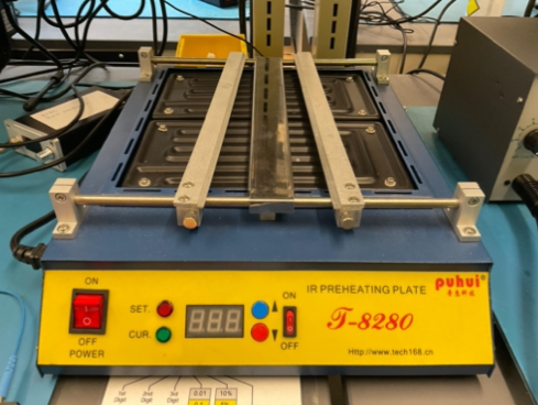
Manufacturer: PUHUI Model: T-8280 Key Specs: 1500W over 280x270mm Manual
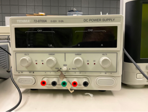
Test and Measurement
Manufacturer: TENMA Model: 72-8700A Key Specs: Dual 0-32V, 0-5A constant voltage (CV) or constant current (CC) outputs, either independent or tracking Manual
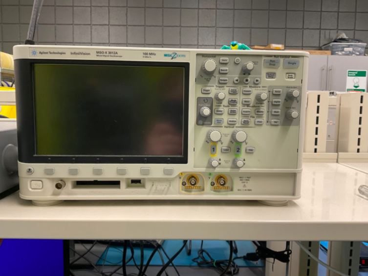
Manufacturer: Agilent (now Keysight), Model: MSOX-3012A Key Specs: 100 MHz 2 Analog Plus 16 Digital Channels 4 million point memory Built in serial bus decoders and protocol checkers for I2C, UART, CAN, etc. Notes: To use the 16 Digital Channels ask for the ribbon cable – take incredibly good care of it, they cost >$500 each Calibrate probes to each scope channel – critical if measuring one signal vs. another. Set any switch to X10 and use the calibrate menu under the channel menu (page 70) Manual
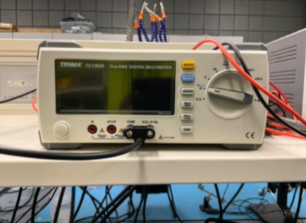
Manufacturer: TENMA Model: 72-13620 Key Specs: Measures capacitance, inductance, and frequency (C, H, and Hz) Two current sockets on the DMM, one for 0-600mA and one for 600mA-10A If you exceed these limits it will blow a fuse but the DMM will still work for voltage and resistance Detect a blown current fuse in the DMM by measuring its resistance – if open circuit fuse blown Manual