| Problem statement Solution video |
DISCUSSION THREAD
DISCUSSION
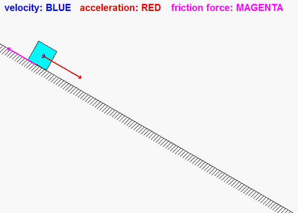
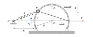
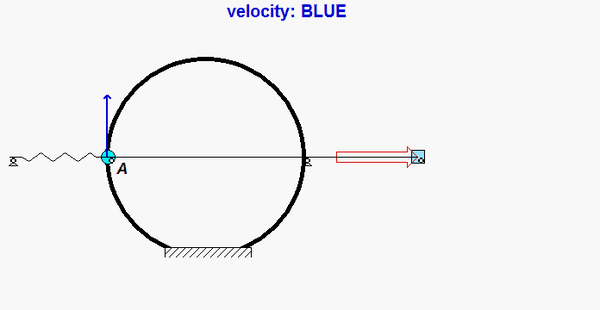
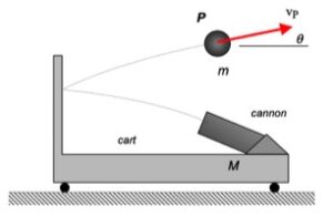
As P moves along the rough incline, the friction force will always oppose the motion of the block. As you see above, the friction force points up the incline as the velocity of the block points down the incline. Be sure to capture this in your FBD.
Hints:
You should follow the four-step solution plan described in the lecture book, and as discussed in lecture:
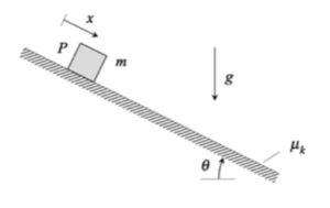
Step 1: Free body diagram (FBD) – Draw an FBD of P alone.
Step 2: Kinetics – Write down Newton’s 2nd law for P.
Step 3: Kinetics – Newton’s 2nd law relates the forces acting on P to its acceleration. In this problem, you are asked to relate the speed of P to the distance that it travels along the incline. To this end, it is recommended that you use the chain rule to convert the acceleration to speed through x: a = v*(dv/dx).
Step 4: Solve – Solve for the speed through the integration of Newton’s section law in terms of x.
Ask and answer questions below. You will learn from both asking and answering.