| Problem statement Solution video |
DISCUSSION THREAD
Any questions?? Please ask/answer questions regarding this homework problem through the “Leave a Comment” link above.
Discussion
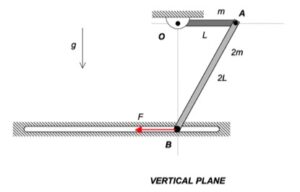
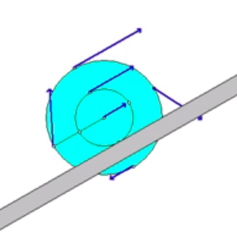
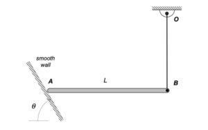
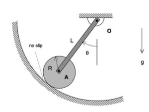
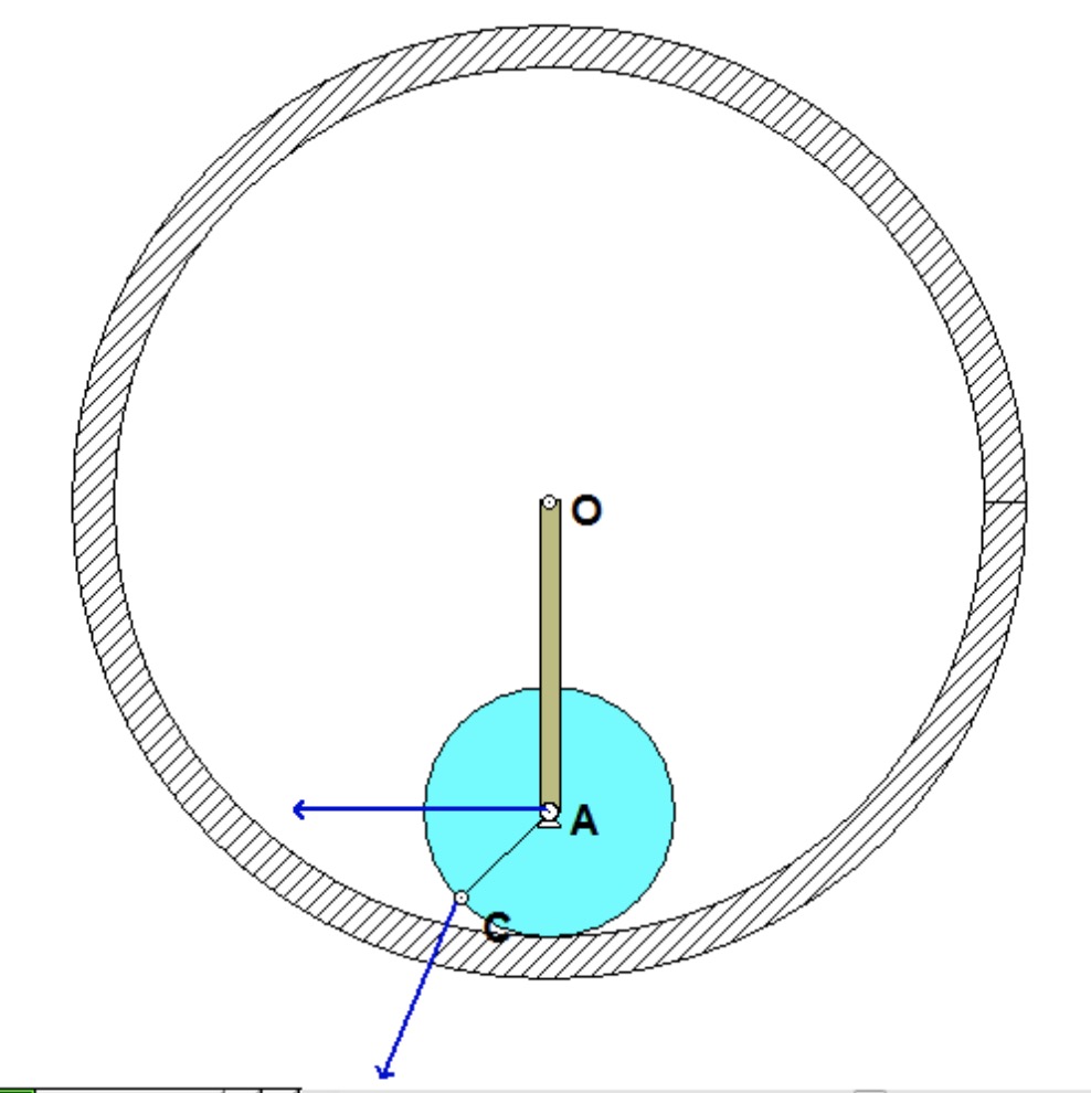
The animation shown above demonstrates the kinematics of the motion of the bar/disk system. The bar rotates about end O. The disk is pinned to end A of the bar, and rolls without slipping on the fixed circular surface. Since the disk rolls without slipping, when point C on the outer circumference of the disk is in contact with fixed ground, the velocity of C is zero. You can readily see this in the animation above.
The instant center (IC) for the disk is the contact point of the disk with the fixed surface. Note the relative sizes of the speeds of A and C in comparison to their distances from the IC. When are the speeds the same? At what positions is the speed of C twice that of the speed of A?
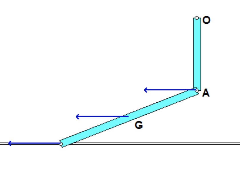
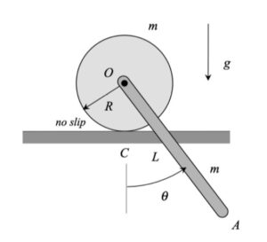
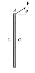
You are asked to determine the rotation rate of the bar when the bar reaches the vertical position shown below.
HINT: As always, we should follow the four-step plan for solving this problem.
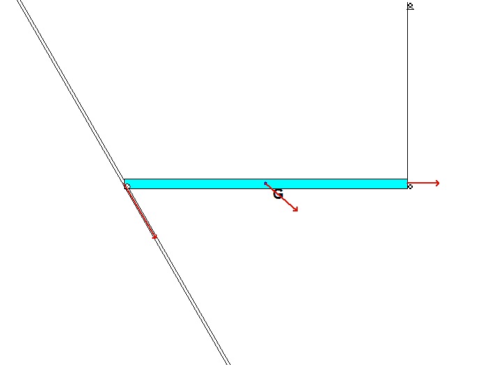
STEP 1: FBD. We will be using the work/energy equation to determine this angular speed. Based on earlier recommendations, we will make the choice of our system BIG, including the bar, and disk together.
STEP 2: Kinetics (here, work/energy). The total kinetic energy of the system shown in your FBD above is that of the bar + that of the disk. For the bar, it is recommended that you choose the fixed point O as your reference point for the KE. For the disk, it is recommended that you choose the center of mass A. Be sure to identify the datum line for the gravitational potential energy, and use this in writing down this potential.
STEP 3: Kinematics. You need to relate the speed of A to the angular speeds of the bar and of the disk.
STEP 4: Solve