| Problem statement Solution video |
DISCUSSION THREAD
Ask and answer questions here. You learn both ways.
DISCUSSION and HINTS
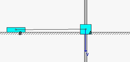
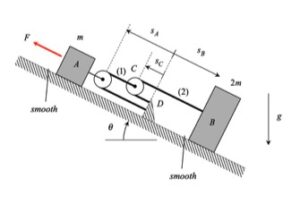
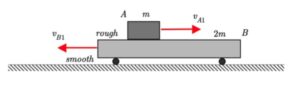
Initially Block A slides to the right along Block B which is traveling to the right. However, with friction acting between A and B, both A and B slow down. At some point, A instantaneously comes to rest, and the starts to move to the left. Once the speed of A to the left matches that of the speed of B to the left, the two stick and move together. You can see this in the animation that follows.
Recall the following four-step plan outline in the lecture book and discussed in lecture:
Step 1: FBDs
Draw single free body diagram (FBD) for the entire system (A+B). Do NOT consider A and B in separate FBDs because you will need to deal with the friction force acting between A and B (which you do not know).
Step 2: Kinetics (linear impulse/momentum)
Consider all of the external forces that you included in your FBD above. If there are no external forces acting in the horizontal direction (x-direction) on your system, the linear momentum in the x-direction is conserved.
Step 3: Kinematics
As described above, A comes to rest with respect to B when vA = vB.
Step 4: Solve
Combine your kinetics equation from Step 2 with your kinematics that you found in Step 3, and solve for the velocity of B.
QUESTION: Are you surprised that your answer for the final speed of B (and A) does not depend on the coefficient of friction acting between A and B? I was the first time that I worked the problem. 🙂