| Problem statement Solution video |
DISCUSSION THREAD
Any questions?? Please ask/answer questions regarding this homework problem through the “Leave a Comment” link above.
Discussion
.
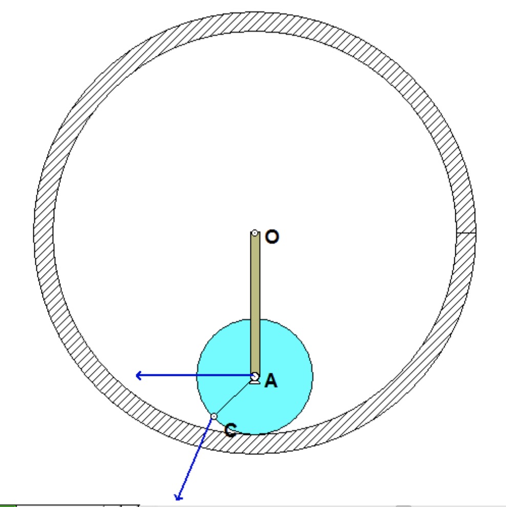
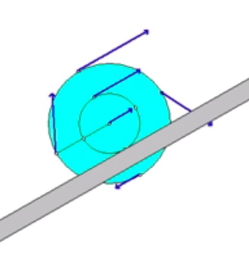
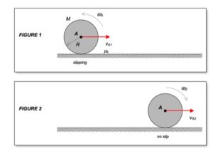
The animation shown above demonstrates the relationship between the translation velocity of the disk’s center A and the angular velocity of the disk. Recall that the disk is initially projected to the right with an initial velocity of A and a counterclockwise rotation rate; that is, the disk is given a “backspin” on release.
As the disk slides, the friction with the floor does two things: it slows down the translational motion of the disk, and exerts a clockwise moment on the disk reducing the rotational rate of the disk. At some point the rotation rate changes from counterclockwise (positive) to clockwise (negative). And shortly after that, slipping ceases to exist between the disk and the floor. Rolling without slipping starts at the point where the plots of velocity of A and angular velocity of the disk go “flat”.
HINT: As always, we should follow the four-step plan for solving this problem.
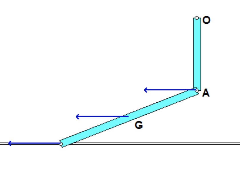
STEP 1: FBD. Here, draw a free body diagram of the disk.
STEP 2: Kinetics (here, linear and angular impulse momentum equations).
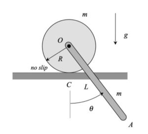
STEP 3: Kinematics. Slipping ceases when the velocity of the contact point on the disk with the ground goes to zero. At that point: vA = ω x rA/C, where C is the point on the disk in contact with the ground.
STEP 4: Solve