| Problem statement Solution video |
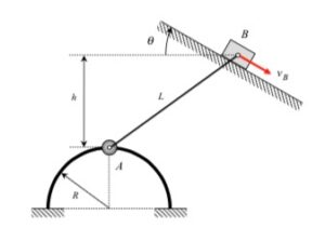
NOTE: Please use θ = 30* when solving.
DISCUSSION THREAD
Any questions??
DISCUSSION
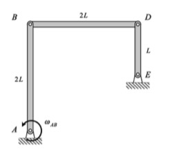
In some sense, this is a very standard kinematics of rigid bodies problem. A rigid link connects points A and B. To relate the motion of these two points, you will need the following kinematics equations:
vA = vB + ω x rA/B
aA = aB + α x rA/B – ω2 rA/B
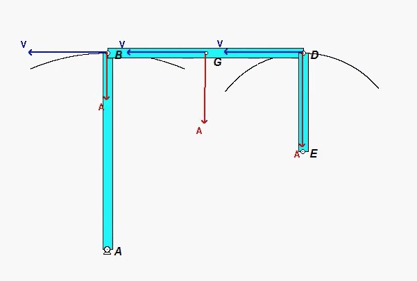
The nuance in this problem is the acceleration of point A. From what we learned earlier in the semester, the acceleration of a point can be written in terms of its path coordinates; that is, here the acceleration of A can be resolved into its tangential and normal components. As you proceed on this problem, you first need to recognize the tangential and normal unit vectors, et and en, for the motion of A. Then write down the acceleration of A, first in its path components, and then in its Cartesian component. In the end, you will have two scalar equations coming from the rigid body acceleration equation in terms of two unknowns.