| Problem statement Solution video |
DISCUSSION THREAD
Any questions?? Please ask/answer questions regarding this homework problem through the “Leave a Comment” link above.
| Problem statement Solution video |
DISCUSSION THREAD
Any questions?? Please ask/answer questions regarding this homework problem through the “Leave a Comment” link above.
| Problem statement Solution video |
DISCUSSION THREAD
DISCUSSION
Using the four-step plan:
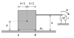
STEP 1: Free body diagram (FBD) – Draw an FBD of bar AB.
STEP 2: Kinetics – Write down the Newton/Euler equations for the bar based on your FBD above. For the “short form” of the Euler equation, please note that you are constrained to using a moment about the center of mass G since there are no fixed points on AB; that is, you should use ΣMG = IG α.
STEP 3: Kinematics – With the inextensible cable being taut, all points on the rigid body AB have the same acceleration, and the angular acceleration of AB is zero: α = 0.
STEP 4: Solve – Use the equations from STEPS 2 and 3 to solve for the tension in the cable and the reaction at on the bar at A.
Any questions?? Please ask/answer questions regarding this homework problem through the “Leave a Comment” link above.
| Problem statement Solution video |
DISCUSSION THREAD
DISCUSSION
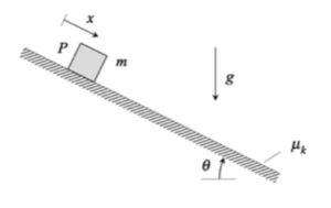
As P moves along the rough incline, the friction force will always oppose the motion of the block. As you see above, the friction force points up the incline as the velocity of the block points down the incline. Be sure to capture this in your FBD.
Hints:
You should follow the four-step solution plan described in the lecture book, and as discussed in lecture:
Step 1: Free body diagram (FBD) – Draw an FBD of P alone.
Step 2: Kinetics – Write down Newton’s 2nd law for P.
Step 3: Kinetics – Newton’s 2nd law relates the forces acting on P to its acceleration. In this problem, you are asked to relate the speed of P to the distance that it travels along the incline. To this end, it is recommended that you use the chain rule to convert the acceleration to speed through x: a = v*(dv/dx).
Step 4: Solve – Solve for the speed through the integration of Newton’s section law in terms of x.
Ask and answer questions below. You will learn from both asking and answering.
| Problem statement Solution video |
DISCUSSION THREAD
DISCUSSION
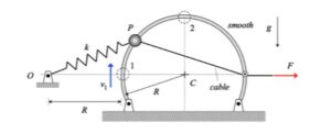
Since the problem asks for a relationship between the change of speed of P and the distance traveled by P, the work/energy equation is a natural method of choice. Recall that with the work/energy equation, we typically want to include as much in the system in order so that we can make as many forces to be workless, internal forces within the system. To this end, consider a system made up of P and the cable connected to P.
Hints:
You should follow the four-step solution plan described in the lecture book:
Step 1: Free body diagram (FBD) – Draw an FBD of the system made up of P, the spring and the cable. Which forces in your FBD do work on the system?
Step 2: Kinetics – Write down the work/energy equation for the system, and the terms included in this equation.
Step 3: Kinetics – In order to determine the work done on the system by the applied force F, you need to find the distance traveled by the end of the cable as P moves from position 1 to position 2. HINT: This distance is equal to the amount of cable that is pulled over the pulley as P moves from position 1 to position 2.
Step 4: Solve – Solve for the final speed of P at position 2.
Ask and answer questions below. You will learn from both asking and answering.
| Problem statement Solution video |
DISCUSSION THREAD
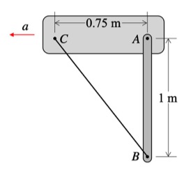
Please note that this question is asking for the VELOCITY of B, not the speed of B. The velocity of B will have two components, and you are asked to find these components.

Discussion and hints
Recall the following four-step plan outline in the lecture book and discussed in lecture:
Step 1: FBDs
Draw a free body diagram of the system made up of B, bar AB and the spring.
Step 2: Kinetics (angular impulse/momentum and work/energy)
Note that all forces on the system act at the fixed point O. What does this say about the angular momentum of the system about point O? Also, consider the work/energy equation for the system.
Step 3: Kinematics
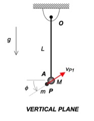
The kinematics of P are best written in terms of polar coordinates R and φ.
Step 4: Solve
Solve for the R and φ components of velocity of P from these equations.
Any questions?
| Problem statement Solution video |
DISCUSSION THREAD
Any questions?? Please ask/answer questions regarding this homework problem through the “Leave a Comment” link above.
Discussion
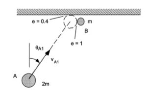
You are asked to investigate the dynamics of this system during the short time of impact of P with A.
HINTS:
STEP 1 – FBD: Draw a SINGLE free body diagram (FBD) of the system of A+P+bar.
STEP 2 – Kinetics: Consider the discussion above in regard to conservation of angular momentum about point O. Recall how to calculate the angular momentum about a point for a particle.
STEP 3 – Kinematics: At Instant 2, the P sticks to A: vP2 = vA2.
STEP 4 – Solve.
| Problem statement Solution video |
DISCUSSION THREAD
Ask and answer questions here. You learn both ways.
DISCUSSION and HINTS
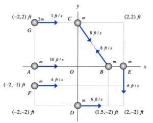
Recall the definition of angular momentum of a particle P (of mass m) about a fixed point O: HO = m rP/O x vP.
For this problem, use this equation to find the angular momentum for each particle and add these together. As you work the problem, consider the number of cancellations that occur among these terms and consider why these cancellations occur. This will help you get insights on the meanings of angular momentum.
| Problem statement Solution video |
DISCUSSION THREAD

Discussion and hints
Recall the following four-step plan outline in the lecture book and discussed in lecture:
Step 1: FBDs
Draw a free body diagram of P.
Step 2: Kinetics (angular impulse/momentum and work/energy)
Note that all forces acting on P in the plane of the table point toward the fixed point O. What does this say about the angular momentum of P about point O? Also, consider the work/energy equation for P.
Step 3: Kinematics
The kinematics of P are best written in terms of polar coordinates R and φ.
Step 4: Solve
Solve for the R and φ components of velocity of P from these equations.
Any questions?
| Problem statement Solution video |
DISCUSSION THREAD
NOTE: B is initially at rest when it is impacted by A.
Any questions?? Please ask/answer questions regarding this homework problem through the “Leave a Comment” link above.
Discussion and hints
The four-step solution procedure:
| Problem statement Solution video |
DISCUSSION THREAD
Any questions?? Please ask/answer questions regarding this homework problem through the “Leave a Comment” link above.
Animation

HINTS:
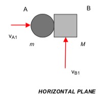
STEP 1 – FBD: Draw three free body diagrams (FBDs): A, B and A+B.
STEP 2 – Kinetics: From the FBD of A, we know that it will continue to move along the same line of travel. In addition, the FBD of B shows that the t-component of velocity for B will remain unchanged, where the “t“-direction is tangent to the plane of contact of A and B. In the n-direction (perpendicular to the t-direction), you have both the linear-impulse equation and the coefficient of restitution equation.
STEP 3 – Kinematics
STEP 4 – Solve: Solve for M and e from your two kinetics equations above.
COMMENT: This problem is posed in a somewhat “backward” way as compared to many problems in impact. Typically mass and COR parameters are given, and we solve for final velocities. Here we are given some information on the final velocities, and we are asked to find mass and COR values. You use the same equations for either type of problem, you just solve these equations in a different way.