All posts by CMK

Homework H4.C – Sp26

Problem statement
Solution video

DISCUSSION THREAD

Any questions?? Please ask/answer questions regarding this homework problem through the “Leave a Comment” link above.


Discussion

FOUR-STEP PLAN

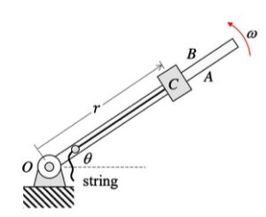
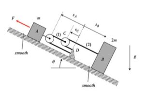
Step 1: FBD – Draw individual free body diagrams of A and B, along with an FBD of pulley C.

Step 2: Newton – From each FBD, write down the Newton’s equation for components along the incline. Recall that the pulley has negligible mass.

Step 3: Kinematics – You will need to use the cable-pulley system kinematics that we worked with earlier in the semester. Please review the material from Section 1.D of the lecture book to relate the accelerations of blocks A and B.

Step 4: Solve – Combine your equations from Steps 2 and 3 to solve for the accelerations of blocks A and B.

Homework H4.A – Sp26

Problem statement
Solution video

DISCUSSION THREAD

Since the motion of P is being described here in terms of polar variables of r and θ, it is recommended that you use a polar description for your forces and acceleration.

Use the Four-Step solution plan outlined in the lecture book:

Step 1 – FBD: Draw a free body diagram of C. NOTE: The arm rotates about a vertical axis, meaning that the arm moves in a horizontal plane; that is, the gravitational force acts perpendicular to the plane of the paper.

Step 2 – Kinetics (Newton): Resolve the forces in your FBD into their polar components. Sum forces in the r-direction and set equal m*ar. Sum forces in the θ-direction and set equal to m*aθ

Step 3 – Kinematics: Use the polar kinematics descriptions of ar = r_ddot – r*θ_dot^2 and aθ = r*θ_ddot + 2*r_dot*θ_dot.

Step 4 – Solve. When solving for the normal force, N, acting on C take note of the sign on your answer. What does this sign mean in terms of answering Part (c)?


Any questions?? Please ask/answer questions regarding this homework problem through the “Leave a Comment” link above.


Homework H4.B – Sp26

Problem statement
Solution video

DISCUSSION THREAD


Please note that since P is not sliding on the rotating guide, P is traveling along a horizontal circular path having a radius with the radius r being the perpendicular distance from P to the vertical shaft. It is recommended that you use a set of polar coordinates: er pointing outward from the vertical shaft to O; eφ tangent to the above-described path of P; and, k pointing upward.

Use the Four-Step solution plan outlined in the lecture book:

Step 1 – FBD: Draw a free body diagram of P. With the guide being smooth, there will be only two forces acting on P: the weight and the normal force N from the rotating guide.

Step 2 – Kinetics (Newton): Resolve the forces in your FBD into their polar components. Sum forces in the r-direction and set equal m*ar. Sum forces in the k-direction and set equal to 0 (since P has no vertical motion for all time).

Step 3 – Kinematics: Use the polar kinematics descriptions of the acceleration of P. Note that r is constant for all time and Ω is constant.

Step 4 – Solve. With the above equations you will have sufficient number of equations to solve for the unknowns in the problem, which includes N and θ.


Any questions?? Please ask/answer questions regarding this homework problem through the “Leave a Comment” link above.


Homework H3.I – Sp 26

Problem statement
Solution video

DISCUSSION THREAD

Any questions??


Discussion and hints:

Your first decision on this problem is to choose your observer. Since an observer on the tube will have the simplest view of the motion of the particle P, attaching the observer to the tube is recommended. Also, attach you xyz-axes to the tube.

Next write down the angular velocity and angular acceleration of the tube. Based on what we have been doing up to this point in Chapter 3, hopefully it is clear that the tube (and observer) has two components of angular velocity: Ω about the fixed X-axis and θ_dot about the moving z-axis. Take a time derivative of the angular velocity vector to find the angular acceleration of the tube (observer).

Following that, determine the motion of the particle P as seen by the observer on the tube.

Use these results with the moving reference frame kinematics equation to determine the velocity and acceleration of the particle P.

Homework H3.J – Sp 26

Problem statement
Solution video

DISCUSSION THREAD

Any questions??


Discussion and hints:

Your first decision on this problem is to choose your observer. Since an observer on the plate will have the simplest view of the motion of the insect, attaching the observer to the plate is recommended. Also, attach your xyz-axes to the plate.

Next write down the angular velocity and angular acceleration of the plate. Based on what we have been doing up to this point in Chapter 3, hopefully it is clear that the plate (and observer) has two components of angular velocity: Ω about the fixed X-axis and θ_dot about the moving z-axis. Take a time derivative of the angular velocity vector to find the angular acceleration of the plate (observer).

Following that, determine the motion of the insect as seen by the observer on the plate.

Use these results with the moving reference frame kinematics equation to determine the velocity and acceleration of the insect.


Homework H3.G – Sp 26

Problem statement
Solution video

DISCUSSION THREAD

Any questions??


Discussion and hints:

It is recommended that you use an observer attached to the boom. As we have discussed in class, your choice of observer directly affects four terms in the acceleration equation: ω and α  (how the observer moves), and the relative velocity and relative acceleration terms (what the observer sees). Note that the remainder of the discussion here is based on having the observer attached to the boom.

The boom shown above has TWO components of rotation:

  • a rotation rate of Ω about a fixed axis (the “+” Y-axis), and,
  • a rotation rate of θ_dot about a moving axis (the “+” z-axis)

(Be sure to make a clear distinction between the lower case and upper case symbols.)

Therefore, the angular velocity of the wheel is given by:

ω = Ω J + θ_dot k

The angular acceleration vector α is simply the time derivative of the angular velocity vector ω : α = dω/dt. In taking this time derivative,

  • Recall that the J-axis is fixed. Since J is fixed, then dJ/dt = 0.
  • Recall that the k-axis is NOT fixed. Knowing that, how do you find dk/dt?

With the observer attached to the boom, what motion does the observer see for point P? That is, what are (vP/O)rel and (aP/O)rel?

NOTE: Pay particular attention to the motion of the reference point O. What path does O follow? And, based on that, how do you write down the acceleration vector of point O, aO?


Homework H3.H – Sp 26

Problem statement
Solution video

DISCUSSION THREAD

Any questions??


Discussion and hints:

It is recommended that you use an observer attached to the wheel. As we have discussed in class, your choice of observer directly affects four terms in the acceleration equation: ω and α  (how the observer moves), and the relative velocity and relative acceleration terms (what the observer sees). Note that the remainder of the discussion here is based on having the observer attached to the wheel.

The wheel shown above has TWO components of rotation:

  • a rotation rate of ω1 about a fixed axis (the “+” Y-axis), and,
  • a rotation rate of ω2 about a moving axis (the “+” z-axis)

(Be sure to make a clear distinction between the lower case and upper case symbols.)

Therefore, the angular velocity of the wheel is given by:

ω = ω1J + ω2 k

The angular acceleration vector α is simply the time derivative of the angular velocity vector ω : α = dω/dt. In taking this time derivative,

  • Recall that the J-axis is fixed. Since J is fixed, then dJ/dt = 0.
  • Recall that the k-axis is NOT fixed. Knowing that, how do you find dk/dt?

With the observer attached to the wheel, what motion does the observer see for points A and B? That is, what are (vA/O)rel and (aA/O)rel, and (vB/O)rel and (aB/O)rel?

NOTE: Pay particular attention to the motion of the reference point O. What path does O follow? And, based on that, how do you write down the acceleration vector of O, aO?


Homework H3.E – Sp 26

Problem statement
Solution video

DISCUSSION THREAD


Any questions??


Discussion and hints:

The disk shown above has TWO components of rotation (note that ω0 = 0):

  • a rotation rate of θ_dot about a fixed axis (the “+” K-axis), and,
  • a rotation rate of ωdisk about a moving axis (the “-” x-axis)

(Be sure to make a clear distinction between the lower case and upper case symbols.)

Therefore, the angular velocity of the disk is given by:

ω =θ_dot* K – ωdisk i

The angular acceleration vector α is simply the time derivative of the angular velocity vector ω : α = dω/dt. In taking this time derivative,

  • Recall that the K-axis is fixed. Since K is fixed, then dK/dt = 0.
  • Recall that the i-axis is NOT fixed. Knowing that, how do you find di/dt?


Homework H3.F – Sp 26

Problem statement
Solution video

DISCUSSION THREAD


Any questions??


Discussion and hints:

It is RECOMMENDED that you choose to put your observer on the disk. In that case, the ω and α  that go into your acceleration equation will be that of the disk.

The discussion below follows a choice of putting the observer on the disk.

The disk shown above has TWO components of rotation:

  • a rotation rate of ω0 about a fixed axis (the “-” Z-axis), and,
  • a rotation rate of ωdisk about a moving axis (the “+” y-axis)

(Be sure to make a clear distinction between the lower case and upper case symbols.)

Therefore, the angular velocity of the disk is given by:

ω = -ω0K + ωdisk j

The angular acceleration vector α is simply the time derivative of the angular velocity vector ω : α = dω/dt. In taking this time derivative,

  • Recall that the K-axis is fixed. Since K is fixed, then dK/dt = 0.
  • Recall that the j-axis is NOT fixed. Knowing that, how do you find dj/dt?