| Problem statement Solution video |
DISCUSSION THREAD
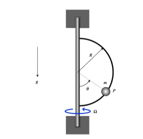
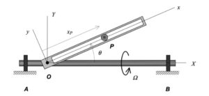
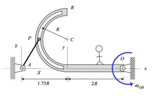
Please note that since P is not sliding on the rotating guide, P is traveling along a horizontal circular path having a radius with the radius r being the perpendicular distance from P to the vertical shaft. It is recommended that you use a set of polar coordinates: er pointing outward from the vertical shaft to O; eφ tangent to the above-described path of P; and, k pointing upward.
Use the Four-Step solution plan outlined in the lecture book:
Step 1 – FBD: Draw a free body diagram of P. With the guide being smooth, there will be only two forces acting on P: the weight and the normal force N from the rotating guide.
Step 2 – Kinetics (Newton): Resolve the forces in your FBD into their polar components. Sum forces in the r-direction and set equal m*ar. Sum forces in the k-direction and set equal to 0 (since P has no vertical motion for all time).
Step 3 – Kinematics: Use the polar kinematics descriptions of the acceleration of P. Note that r is constant for all time and Ω is constant.
Step 4 – Solve. With the above equations you will have sufficient number of equations to solve for the unknowns in the problem, which includes N and θ.
Any questions?? Please ask/answer questions regarding this homework problem through the “Leave a Comment” link above.