| Problem statement Solution video |
DISCUSSION THREAD
We encourage you to interact with your colleagues here in conversations about this homework problem.
DISCUSSION
As always, we should follow the four-step plan:
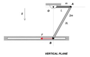
STEP 1: FBD
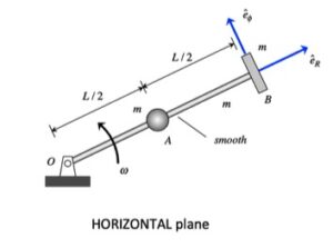
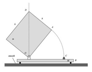
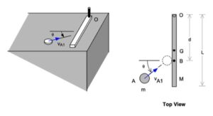
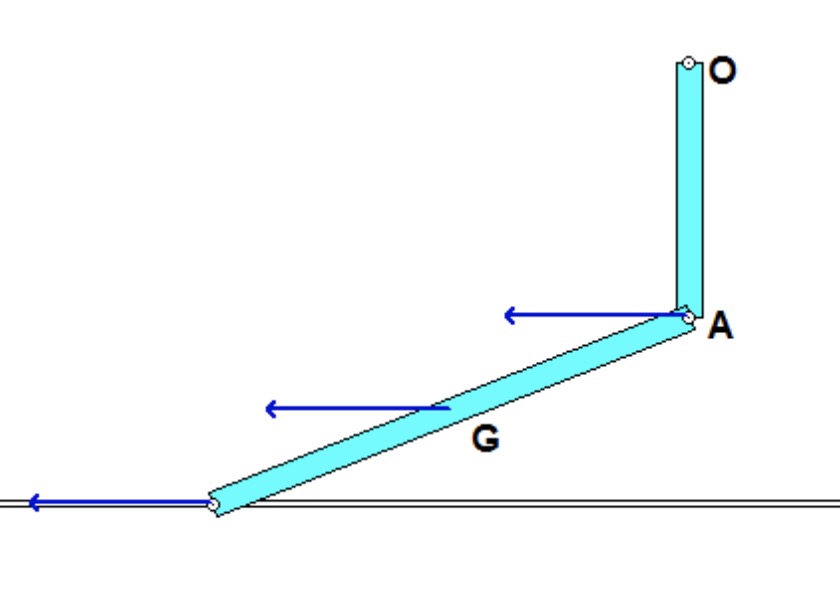
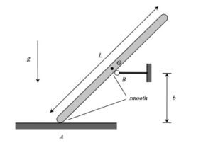
Draw an FBD of the bar. Since the support at B is smooth, the reaction on the bar at B will be perpendicular to the bar.
STEP 2: Kinetics
You should write down the two Newton equations, and the Euler equation. As always, take care in choosing your reference point for Euler’s equation. Since we have no fixed points for the bar, you should choose the center of mass G as your reference point.
STEP 3: Kinematics
Note that the path of the center of mass G is tangent to the surface of the bar (that is, the bar can move only along the support, not into the support). With the bar being released from rest, the acceleration of G is tangent to the path. Specifically, the acceleration of G is directed along the direction of the bar. Write down the rigid body kinematics equation that relates the accelerations of A and G. This vector equation represents two scalar equations (x- and y-components).
STEP 4: Solve
At this point, you will have three kinetics equations and two kinematics equations, for a total of five equations. You will have five unknowns. Solve!