| Problem statement Solution video |
DISCUSSION THREAD
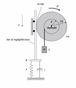
NOTE: Please replace the cable on the left by a rigid bar of negligible mass.
Discussion and hints:
Shown below is an animation of the results of a simulation of the motion corresponding to an UNDERDAMPED system. The response is oscillatory, however, the amplitude of the response decays away at an exponential rate.
For this problem, you are asked to determine the amount of damping (i.e., the value of c) for which the system is CRITICALLY damped (ζ = 1). The animation below shows the response of such a critically damped system. Not that with this value for the damping ratio ζ, the oscillations are damped out, with the response asymptotically approaching the steady-state static equilibrium state.
The derivation of the dynamical equation of motion (EOM) for a system is a straight-forward application of what we have learned from Chapter 5 in using the Newton-Euler equations. The goal in deriving the EOM is to end up with a single differential equation in terms of a single dependent variable that describes the motion of the system. Here in this problem, we want our EOM to be in terms of θ(t).
Recall the following four-step plan outline in the lecture book and discussed in lecture:
Step 1: FBDs
Draw individual FBDs of the drum and the bar. Define a translation coordinate, x, for the bar.
Step 2: Kinetics (Newton/Euler)
Write down the Newton/Euler equations for the drum and the bar.
Step 3: Kinematics
Use the no-slip condition between the drum and the bar to relate x to θ.
Step 4: EOM
Combine your Newton/Euler equations along with your kinematics to arrive at a single differential equation in terms of the dependent variable θ.
You will then need to find the static rotation of the disk from your EOM. Also, put the EOM in “standard form” in order to find the undamped natural frequency ωn and the damping ratio ζ of terms of the given parameters for the system. Critical damping corresponds to ζ = 1.
Any questions?
the image in the hints and the image in the problem PDF are different; which one should we consider for our solution? or can these systems be thought of as the same?
Do we act like the cable pushes down and is taut all the time?
I think you can assume the cable is taut the whole time, and the direction of your tension doesnt matter as long as its equal and opposite.
I agree with this comment. By making sure that the direction of your tension on the drum is equal and opposite to the direction on each block with the same cable, the math should all work out well in the end. Since the cable is stated not to slip on the drum, you can use instant centers to relate the motion of each block with the turning of the fixed drum and solve for each tension in terms of the other variables. Hope this helps!
In reality, the cable would have slack when rotated counter-clockwise. However, for the problem to be more realistic, the rope can be replaced with a massless bar. The FBDs should be the same regardless though.
I agree with this, and I think the rigid bar part basically avoids the slack issue completely, so we can just treat it like it’s always acting.
Yes! The blog has been updated to say to replace the cable with a rod.
because the problem says the cables do not go slack, you can assume that this tension is maintained throughout the entire motion.
The mathematical modeling is the same for the two.
I believe you can think of them as the same system as long as you assume the cable does not go slack. With the bar, instead of having a tension force, you have a friction force at the no slip point.
As long as the systems are kept consistent, I don’t think it matters which one you use. It just might be easier one way or another.
is e) just asking us to prove that zeta = 1 when C/2Mw = c/sqrt(km)
Part (e) is asking you to find the damping coefficient c that makes zeta = 1.
it actually wants you to use your equivalent mass and stiffness terms to find the damp. coeff
When part e) says use R/Ko = 1, is that also referring to using zeta = 1 for critical damping? I’m just confused on that part.
I think when part e.) tells us to use that relation, they want us to set R equal to Ko to simplify the math. We also use zeta equals 1 for critical damping. I found it helpful for this part to use the standard form of the EOM and then use the relation that the xdot term equals 2*zeta*natural frequency.
I agree with this, putting it in standard form first helped me see where the damping term comes from. Then setting zeta = 1 makes it pretty straightforward to solve for c.
for parts a) and e), why is the spring displacement 2Rtheta instead of just Rtheta, and how would squared term affect the EOM?
I believe it’s due to the fact that the spring is at point B and the motion of the disk is dictated by the outer radius because it’s attached to the outside rather than the inside. The connecting cable will always be 2R away from the center of rotation. For the EOM, the component squared term would be 4kR^2theta to factor in the displacement and the radius.
This would be because the spring is connected to the outer radius which is 2R
The spring displacement is 2Rtheta since the body that the spring and dampener are connected to interacts with the outside of the drum, which has radius 2R. When using the rigid body equation you find that x =radius * theta, and the radius in this case is 2R. If the body interacted with the inner part of the drum with radius R, then the displacement would be Rtheta.
It’s 2Rtheta because the spring’s cable is wrapped around the outer drum with radius 2R. The term gets squared because calculating torque means multiplying the spring force by that exact same 2R distance.
When writing the equation of motion, is it better to treat the system entirely in terms of the rotational coordinate theta from the start, or would it also be valid to first write separate equations for mass A and the drum and then combine them using the no-slip constraints?
I believe writing two seperate FB’s is the best, and then relating the coordinates using kinematics in order to get them in the same coordinates.
I agree with you here, Tanish, I created separate FBD’s for the drum and the mass A and related them using kinematics. I found this method easier than using one FBD for the mass A and the drum.
I agree with this, doing separate FBDs made it way easier for me to keep track of everything. Trying to do it all at once in terms of theta got confusing.
I also believe for all spring-mass problems solved using Newton’s equations, it’s best to use separate FBDs. For other problems on the final (such as angular momentum), however, it’s better to draw a large system.
I believe separate equations and FBDs allows for a better breakdown in this situation.
Both approaches are entirely valid and will result in the exact same equation of motion. Writing separate equations is great if you need to find the internal cable tensions, but deriving it directly in terms of theta using an energy or equivalent system method is usually much faster.
For part b, when finding theta st, can I just set all velo and accel to 0 and set the torques from gravity the spring equal to each other or do I have to consider drum inertia?
For any problem, first derive the EOM in terms of the desired dependent variable. The static deformation can then be found by setting the first and second time derivative of the dependent variable equal to zero. This is provide you with an algebraic equation that can be solved for the static deformation.
Yes you can, as at the equlibrium one the velocity and acceleration will be zero as nothing is moving nor accelerating.
For the spring displacement, is the reason it becomes 2Rθ because the spring is attached to the outer radius and the cable unwraps over that full distance?
Yes, because the cable does not slip it will wind 2Rtheta, therefore also pulling connector B 2Rtheta displacing the spring that same amount as well
If you’re talking about the kinematics at the no slip point, yes. recall that x = Rθ, wherein this case, it is a distance 2R from the no slip point and the center O.
Yeah, I think the key idea is that the spring is connected at the outer radius, not the inner one. Since there’s no slip, the arc length at that contact point is what drives the spring displacement.
So because that point is 2R from the center, the linear displacement becomes x=2Rθ, even though the inner cable (mass A) only moves Rθ.
Basically, each radius creates its own kinematic relationship.
I am a little stuck on the FBD directions. Is it the correct approach to assume the drum is rotating CW so friction on the drum points downward and friction on the bar points upward with kx and c_dot x pointing downward?
You can assume it is rotating CW but there is no friction involved in this. And yes, kx and c_dot x do point downward while cable tension B is pointed upward.
I believe you are correct. At the no slip point, friction acts downward on the drum as it opposes the direction of motion. The friction on the bar points upward in the opposite direction. Therefore if you assume y+ is upward, kx and cx_dot will be pointing downward.
I was confused about this too, but what helped me was just assuming a direction and staying consistent with the sign convention.
For example, if we take θ positive clockwise, then the left side of the drum moves upward, so the bar displacement x ends up being negative relative to that motion.
For the FBD, as long as the forces between the drum and bar are equal and opposite and the spring/damper opposes motion, the math will correct any wrong assumed direction.
I just want to clarify, when this problem was mentioned in class at Dr. Krousgrill’s 11:30 section, it was recommended to use 2 coordinates: one for the bar and one for Block A. Does this still hold true since the problem changed from a cable to rigid bar or is using 1 coordinate still easier?
It is not a question of it being easier. It is necessary to have a separate variable for the two motions since they are not the same.
I think the best way to view these problems is degrees of freedom. There is rotation (drum) as well as translation (bar). If the drum somehow translated another object laterally from a different point on the drum, the problem would likely require another variable.
How would maintaining the problem statement with a cable complicate the problem or present issues when deriving the system response? Does the problem lay in the cable reaching an unstretched state?
I’d imagine that the math would be similar as long as the drum rotated clockwise, but that it would be difficult to account for the motion if it rotated counterclockwise and the cable went slack.
Do we need to know how to solve these problems if the mass of B is not negligible? Ex if there is another mass connected to springs, would that force translate up the bar to the drum and be included in calculations?
I’m sure it would be, or otherwise it could be added to a different mass in a larger FBD to make calculations easier, or to eliminate any other internal forces that may come with B having a mass.
When deriving the EOM for H6.G, make sure to use the radius of gyration (kO) for the drum’s inertia, so I = 2m * kO^2. Also, note that the spring and dashpot are at the outer radius, so their terms in the EOM should be multiplied by (2R)^2. For part (e), the critical damping calculation simplifies a lot if you substitute R/kO = 1 early on.
What if there was a friction force on the top left surface, how would this affect the question? I believe it would cause the no slip assumption to cease.
If there were friction where the cable contacts the drum the cable tensions on the two sides would no longer be related since they’re in the ideal no slip, frictionless model. I dont think the no slip condition just disappears, but it would mean you couldnt use the same simple cable kinematics and force relations without accounting for friction’s effect on the tension distribution.
“No slip” and “frictionless” are contradictory descriptions of a contacting surface.
Do we draw the FBD including the rigid bar? If not, how do we represent the spring and dashpot acting on the drum since they’re connected to the horizontal bar section?
Yes you do need to draw a separate FBD for the rigid bar. Since it is massless you only have the spring and dashpot forces acting downwards while the cable tension is pointing upward.
I agree with this, treating the bar separately helped a lot since it’s massless and only has the spring/dashpot and tension forces. It made the FBD way clearer for me.
We can draw the FBD including the rigid bar, as there are forces on the problem which will act along the bar, and understanding these forces is paramount to understanding the problem. Hope this helps.
How does the drums rotational inertia combine with the translational effect of the mass of particle A to create the inertia in the EOM?
I am also curious about this. Would it change the EOM equation? Which term would it add to?
I believe it is already accounted for in the EOM – in making the newton-euler equations, you get a sum of forces for the translational motion of the bar, and a moments equation for the rotational motion of the drum. The moments equation considers the translational moment of A as the tension force in the cable that connects to the inner radius of the drum. The EOM is derived from this moment equation and the sum of forces equation.
How does the rotation of the drum couple the translational motion of mass A and the spring–dashpot motion of connector B, and how does that coupling determine the effective inertia and effective stiffness seen in the theta‑coordinate?
When rewriting the EOM in terms of z = θ − θ_st in part (c), why do the gravity and static spring force terms cancel out, and what does this tell us physically about using the “relative to equilibrium” coordinate versus the absolute coordinate θ?
They cancel because θst is the rotation where the constant gravity torque and the constant spring torque are already balanced. Physically, using z = θ – θst means you are measuring motion from the equilibrium position instead of from the original zero position, so the constant offset forces drop out and only the actual vibration motion stays in the equation
θst is the static equilibrium position where the constant gravity torque is already balanced by the spring torque. Defining that coordinate in c means measuring motion about equilibrium, so to my knowledge those terms cancel out, and only vibrational terms are left in the EOM.
Can we assume R/k0 = 1 for everything to simplify things? Or can we only assume that on d?
I believe you would only use that relation on part e as you are focusing specifically on the critically damped case. The rest of the equations should be kept the same.
Why does the hanging mass A contribute both an inertial effect and a gravitational torque in the equation of motion, instead of being treated as just a force?
I don’t think hanging mass A is contributing a moment of inertia as it is not rotating. It only translates. That being said, relating the tangential acceleration of A to the angular acceleration puts both the moment of inertia and tangential acceleration to be times by theta_ddot in the EOM
When I calculated the critical damping ratio, I got a ratio that included other variables besides the c/sqrt(km). Is this incorrect? Since we don’t have values for any of the variables, it feels wrong to have other variables besides the ones they said to have the ratio in terms of.
I don’t think that it automatically means it’s incorrect. Sometimes I’ve seen extra variables appear before the EOM is fully reduced to the standard form. First find the M, C, and K terms and using R/k0 = 1, it should reduce to something more workable.
Would it be better to use two different coordinate systems for this question?
No, it’s better to just use one coordinate system. Everything else moves because of the drum, so a second coordinate would just make it harder.
I think using one coordinate is better since everything is tied to the drum’s motion through the no slip condition. Using two just made it more complicated for me.
In reviewing this problem in lecture, Professor Krousgrill suggested using two coordinate systems (one for translational motion of bar and one for rotational motion of drum) would be efficient. That being said, the two coordinate systems will eventually become one through the use of kinematics so it all turns out the same in the end. I think using two coordinate systems made constructing the Newton-Euler equations easier and the understanding the overall relations between the bar and drum.
For point B, since it’s massless, is it correct that we set Fx=0 instead of using mxdotdot even though it is moving still?
Yes, this would be correct. You would sum forces in that direction to zero because we are assuming that the mass is “0” . This should help simplify the newton equations and allow you to equate the newton and euler equations together.
Should we create separate FBD’s for the bar, the drum, and the particle A or should A be included in one of the other FBD’s. I assume because A is attached to the drum that its motion is dependent on the motion of the drum.
Recall our guiding principle from before: when using the Newton/Euler equations, you should draw individual FBDs of each body in the system.
In this problem, is it okay to use the normal equation for moment of inertia and then substitute R = k_0 at the end?
I keep seeing comments saying there is no friction in this problem. in the 11:30 Krousgrill class he also drew the FBD with no friction specifically no friction at the point of contact between the bar and the drum. If the point of contact is no slip, how can there be no friction?
For the original statement of the attached problem statement, there is a cable between the drum and connector B. For this problem, there will be a tension force acting on the cable. Friction between the cable and the drum is internal; therefore, it does not appear in the FBD.
In the Discussion above, it says that in order for the problem to make more physical sense, we want you to replace the cable by a bar having negligible mass. For that problem, there is a friction force acting between the bar and the drum. An FBD of the bar will shown an equal and opposite friction force.
Both problems are mathematically the same, having the same EOM at the end.
I hope that this helps.
Why is spring displacement 2RTheta and not just RTheta? Is it because it’s on the outer rim?
It’s because that cable is wrapped around the outer radius 2R.
What would change if the bar did not have negligible mass? Would the inertia then play a factor in how the spring force acts?
Because we are assuming the bar has negligible mass, does this mean the m*xd_dot term disappears in the Newton equation for the bar?
Yes, if the bar has a mass of m=0, then mx¨=0, so the force equation just ends up being F=0, meaning that it can still move, but there are no forces acting upon it.
Yes. If the bar has negligible mass, its inertia term goes to zero, so the Newton equation for the bar becomes sum of forces equals zero.
When reading the other comments, it was established to have a tensile force acting upwards on the bar. I am confused how there is a tension force going up for the bar’s FBD. I thought the bar would move up because it is sandwiched between the drum and the wall.
I don’t believe there is a tensile force acting on the bar, but there is a tensile force from particle A which is providing a torque on the drum. There is a friction force acting on the bar, however. This comes from the no-slip condition between the bar and the drum.
How do we relate the displacement of the bar to the rotation Θ using the no-slip condition?
I believe that those two coordinate systems can be linked similarly to previous problems, where the no-slip condition means that the displacement of the bar is equal to the rotation (theta) of the drum multiplied by the outer radius.
Also make sure that your positive x direction is upwards, so that when you do x = R*theta, you don’t have to worry about the sign convention (ex: x = -Rtheta). We choose a positive x direction as upwards because as the disk spins CW, the bar will move up (increase in positive x direction), thus corresponding to the correct sign convention.
Instead of adding a second coordinate system for block A, can we reframe the moment of inertia about point O to include both the block and the drum?
I’d say that block A should be translational inertia first instead of adding it directly to the drum’s moment of inertia. Since A is moving linearly, I think the best thing would be to keep the drums Io separate and write a force equation for A. Then relating A acceleration to theta_doubledot.
If we include the bar, block, and drum as our system For the rotational aspect of the moment of inertia when taking moments about point O, why do we include block A, and not just the drum?
Please recall that when using the Newton/Euler equations, you should draw individual FBDs of the bodies included in the problem. In that case, you are including the rotational inertia of only the drum. A provides translational inertia.
Isn’t the translational inertia equal to the moment of block A, making an FBD of block A unnecessary? Its inertia about O should be mR^2 experiencing an angular acceleration of g/R, and the moment it applies on the drum is mg(R)
What side does the friction force go on the disk and on the bar? I had it as upwards on the disk and downwards on the bar. Help!
Friction is directed opposite to the direction of motion, so I would have it downwards on the disk. However, whether you orient its direction upwards or downwards should not ultimately matter for answering the problem, as long as you are consistent with your signs, and obey Newton’s 3rd law of motion. Hope this helps.
Apologies, I think there is an error in what I have written. The disk does not slip, so the friction here is static, not kinetic, hence the contact point is technically not in motion. The direction of friction would be upwards, not downwards.
I think a key to this problem is correctly identifying the equivalent mass moment of inertia. This is because mass A is attached with a cable its linear inertia mR^2 must be added to the drums rotational inertia. Also since the spring and dashpot are on the outer radius their contributions to the stiffness scales which significantly increases their effect on the systems stability.
Since we are looking at the moment around the drum only, wouldn’t the rotational inertia were interested in be only be the drum? Yes, the block has mass m, but this would only apply a weight force on the drum, which would cause a moment on the drum rather then an additional component of rotational inertia.
This is correct, as the only thing coming from the mass is a tangential force, it is not rigidly attached to the drum like a mass on a bar would be, and therefor does not contribute to the moment of inertia of the drum.
a thing that helped for this problem was to track the cable displacements separately since they are from different drum radii, and after that all the equations for the spring, damper and mass motion could be written in terms of theta.
Since there are two cable radii, is it easier to do the moment about the mass center in terms of theta or go straight to Newton-Euler equations and convert?
Comparing the animations clarified the physical meaning of the critical dampening. Sticking to the 4 step plan was crucial for keeping the kinetics and kinematics organized; it was interesting to see the direct relationship between the physical components and the system’s natural frequency.
With the cable on the left replaced by a rigid bar, does that mean the motion of mass A is directly constrained by the rotation θ without needing to consider tension, or is there still an equivalent force interaction we need to include?
There is still a force interaction. The rigid bar transmits a force (tension or compression) between the drum and particle A, just like the cable did, and that force still appears in both the Newton equation for A and the Euler equation for the drum.
I’m confused on how to convert from using y to theta as a variable. I’m pretty sure you need to use the sum of forces in y to solve it but I can’t figure out how to relate this back so the EOM is in terms of theta.
I’m pretty sure you can link y and theta just by using the inner radius. For example, since mass A is on the inner part of the drum, you just use y = R * theta and y_doubledot = R *theta_doubledot. Then, when you write your Newton equation for mass A in Step 2, you just sub that back in to get the whole EOM in terms of theta.
Would it be better to make a separate FBD for particle A or include it in the FBD of the drum? If including it in the drum FBD, the tension force from the inner cable would be internal and generate no moment, correct?
I think that since the only force that particle A would produce is mg, we could just have that force be on the FBD for the drum.
I just want to make sure I understand the kinematics correctly — since the spring/damper is attached at the outer radius, is the displacement always x=2Rθ regardless of whether we treat the left side as a cable or a rigid bar?
Also, does replacing the cable with a rigid bar change anything in the no-slip relationship, or does it only affect the force transmission in the FBD?
The kinematics are only affected by the drum I believe
Replacing the cable with a bar would change the fact that the bar can go into compression and tension while a cable can only transmit tension, but I do not think it changes anything in the no-slip relationship
Does the bar apply a normal horizontal force onto the drum? I’m still a little confused on how switching from a cable to a bar affects the problem.
x=2Rθ holds regardless of whether the connection is a cable or rigid bar, since it comes purely from the geometry of the outer radius unwinding . Replacing the cable with a rigid bar only affects force transmission in the FBD, allowing the connection to push as well as pull, but leaves the no-slip kinematic constraint completely unchanged.
How do the spring and the bar affect the rotating disc? Is it just through the instant center at the side of the bar and the resulting kinematics relationship? Or does gravity also have an impact?
The bar I believe is simply a way to connect the spring and dashpot to a disk, which is why I believe the mass is specified to be negligible. In this problem, we are just using torques instead of forces, so we are using I * alpha on the right side of our Newton/Euler equations instead of m * x”. The spring and dashpot should induce a torque 2R away from the center of the disk whereas the hanging block induces one that is R away.
How do we know which direction to take for the friction force between the bar and the drum, since its a no slip zone?
What I’ve been doing is simply picking a direction, usually opposing the motion. As others have mentioned, though, if you keep your sign convention consistent, it should work out without issue. Generally its best to have the friction force oppose motion, as that best reflects what’s actually happening.
I saw a lot of discussion on the last homework about how taking the moment at the no-slip point could simplify the problem. Is this a similar situation, and if so, how can we visually go about assessing whether to use the no-slip vs. the origin?
It’s not applicable like that with this problem. The drum is pinned at the origin. you should take the moments of that origin. You should then find your cable velocities.
In my EOM, I just used the tention from the cable. Does the friction force in the no-slip area become the tension force in our torque equation?
no, friction force and cable tension are acting in different locations. f (friction) ends up getting replaced with (kx+cxdot) becuase the bar has no mass
I’m struggling to set up the equation of motion for this system, how do I properly express all forces and energies in terms of θ, particularly when dealing with the two different radii and the attached spring-damper?
What I did was solve for forces in the y direction for two things: bar, particle A. Then, I used Euler’s for the drum. From there, you can equate the different equations to shared variables and come up with one equation.
In this question, I wondered why it was relevant to the static rotation of the drum versus a dynamic EOM. The static theta actually has a mathematical significance where, because the system is oscillating around a shifted position instead of a zero, it would more constant terms to the original EOM, making it much more difficult to solve. In simpler words, the added effect of gravity is counteracted by involving the z term and static theta which makes it more accurate. The system settles around that position and vibrations occur based on that static, rested position. Also, I found it helpful to define the positive x-coordinate upwards since if the positive moment is clockwise, it will make both the block and the spring and damper system move up. This simplifies calculations a lot!