| Problem statement Solution video |
DISCUSSION THREAD
The above simulation results are for a set of generic parameters that may be different from those assigned this semester.
Question: Can you tell from the animation if the excitation frequency ω is smaller than or larger than the natural frequency ωn of the system?
Any questions?? Please ask/answer questions regarding this homework problem through the “Leave a Comment” link above.
Would it make more sense to sum the moments about center of the disks or about each of the 4 no slip points on the wheels?
I believe it would make more sense around the center because then you can have the friction on top and bottom pointing in opposite directions to cancel out
You don’t need to sum about all 4 points, just the bottom of each disk so that the moment equation can include both the friction forces AND spring/excitation forces in the equations. The center would lead to no spring force/excitation force, and therefore the EOM can not be found.
If you use the Euler equation on the center of the disks, you would also need to use the Newton equation for the sum of forces in the given positive x direction to account for all of the forces. With both of these equations for the two FBD’s, you’ll be able to solve for the EOM.
I found it best to sum the moments about the center of the disks so that the frictional forces can be related.
By taking the moments about the center of the disk, you loose both the force from the spring in the left disk and the applied force in the right disk. I believe this doesn’t work to actually find the EOM, but you can certainly try.
How do you handle relating the motion of block C to the rotation of disks A and B under the no-slip condition?
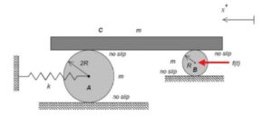
To relate the motion of the block to the disks, we have to look at the instantaneous center of rotation for each disk. Since the disks roll without slipping on the ground, the contact point with the floor is the center of rotation, meaning velocity is zero.
To add onto this, the motion of block C (xddot) can be related to the IC using its distance from it. So if your IC is at the bottom of A, xddot is thetaddot/4R since block C is at the top of the disk.
When calculating the total kinetic energy, should I sum the translational energy of all three masses plus the rotational energy of both disks?
Yes, include the translational kinetic energy of disk A, disk B, and block C, plus the rotational kinetic energy of both disks. Because every part that moves stores kinetic energy. Then use the no-slip conditions to write everything in terms of x.
Yeah, I agree with this — I think the key is to include both translational and rotational KE for each disk, since neither is negligible here.
What helped me was realizing the no-slip conditions basically tie everything back to x dot, so even though it looks like a 3-body system, it really reduces to one DOF. Once you do that, the energy expression becomes much cleaner, and you can identify the equivalent mass pretty directly.
Why are you writing down the work/energy equation? You should be using the Newton-Euler equations to derive the EOM.
For problems like these, what is an easy way of telling if the problem will use the force equation or Newton’s?
If ever in doubt, write down all of the equations. Then choose the ones that you feel will help you the most.
It’s also usually a good sign with springs involved to try Newton/Euler first, as pretty much every vibration question involves a spring. Also if it ever asks for x_st, the EOM, natural frequency, etc is an indication to use Newton/Euler
Do we need to know if there is friction in this system to solve?
There must be friction since we have no slipping between the disks and the ground/block.
The friction between the disks and the ground does not matter if you take the sum of the moments about the no slip point. However, the friction between the disks and the bar is important. It is how you will relate all three bodies to each other.
As a general comment, when you got to draw the FBD, make sure your positive direction of theta is in a direction that will make writing the equations correct. I choose the CCW direction, since the relationship between the points where the disk contacts the block directly relates to the rotation in this direction. (i.e. when the block moves left, the disks rotate CCW)
When calculating the total kinetic energy to find our equivalent mass, we must include both the translation of the disks’ centers and their rotation. Do the different radii (2R vs R) end up canceling out when calculating the rotational kinetic energy (1/2*I*(θdot^2)) for each disk?
Yes, the different radii do cancel out. This is because their moment of inertia and angular velocity are inversely related. with no slip, the angular velocity is proportional to 1/r. Because a homogeneous disc has moment of inertia proportional to r^2. Because you end up squaring the angular velocity, they cancel.
When applying the no-slip condition between the disks and block C, do we need separate kinematic relationships for disk A and disk B, or can everything be expressed directly in terms of the displacement x of block C?
I found it helpful to use two different kinematic eqautions for disk A and B. Because they have different radi, the relation between x (displacement of C) and the angular acceleration of the disks are different.
Although the question specifies that there are no slip points at the top of each block, can I assume that the velocities at those no slip points are nonzero since they are in contact with the bar going left at a velocity of x dot (for when the system is displaced to the right of spring equilibrium)?
Yes I thought no slip does not mean zero velocity necessarily.
Yes, the velocity at the No Slip points between the bar and disks would be equal to the velocity of the bar.
Does the direction we draw the friction force between the disks and block matter as long as they are equal and opposite?
No, the direction doesn’t matter. For the non slip points between the disk and the ground, the sum of the moments should be taken, so direction isnt important at all. The friction between the no slip point on the disks and the bars should be equal and opposite though.
Direction does not matter as long as you are consistent in your direction.
Do I have to describe each body’s movement with a different coordinate system?
I found it helpful to describe the movements of the disks and bar with different coordinate systems for each object. I believe we can use kinematics to relate the different variables if needed.
Would the translation of the large disk be different than the translation of the bar? How would I relate those? I need to find the stretch of the spring.
For the no-slip conditions, should the velocity of block C equal the velocity of the top contact point of each disk, while the bottom contact point has zero velocity relative to the ground? I want to make sure I’m relating x, the disk center motion, and each disk’s angular velocity correctly before writing the Newton/Euler equations.
That’s how I’ve been approaching it. I think at the top contact between block c and the disk, the velocity of that point on the disk matches the velocity of block C.
What exactly is the amplitude of the forced response? Is it the coefficient of the particular solution?
The amplitude of response is sqrt(A^2 + B^2).
When applying the no-slip condition at both the top (block–disk contact) and bottom (disk–ground contact), is it better to write separate kinematic equations for each disk, or can everything be consistently expressed in terms of x of block C right away? I’m a bit unsure how to systematically avoid over-constraining the system when both contacts impose rolling constraints.
I was able to solve using just the x of block C because I used the summation of the moment about that no slip point on the ground for both A and B. This way you get the formulas for f_a and f_b which can be used to create the EOM.
I have my friction forces on the disk at the contact point b/t the disks and the bar pointing to the right. I’m thinking that the friction opposes the direction of the disks which in our case are moving left, therefore the frictions should point opposite, is that plausible?
I would spend no effort trying to determine which way to draw the friction forces on the disks, either at the top or the lower surface. Make a choice. Be sure that the corresponding friction forces on the block are equal and opposite to the friction forces that you chose for the tops of the disks. And, stick with your sign conventions throughout the solution. The math will take care of things.
should we consider different coordinate systems for the block and the two disks?
I would define rotational coordinates for the disks.
Should my FBD include both disks or should they be drawn individually?
Please be reminded that when using the Newton/Euler equations you need to use individual FBDs of the bodies.
Do you know why?
This is because N/E requires rigid bodies.
Since there exists a no slip condition between the bottom surface and top surface of the disks, how do we solve for the EOM and get rid of the friction forces? Additionally, are the friction forces for disk A equal to disk B? If not, then how do we relate the two? A sum of moments around the no slip condition at the surface of the disk still leaves one friction force acting on the bottom surface.
You will have three equations coming from kinetics: a Newton equation for the bar and two Euler equations for the disks. You will develop kinematics equations relating the rotations of the disks to the translation of the block. Combine these equations through the elimination of the two friction forces that you mention. From that, you have the EOM.
The amplitude of the forced response is always going to be f_o, correct? Amplitude doesn’t depend on the frequency of the system, unless I am mistaken.
I thought that amplitude was sqrt(A^2 + B^2) which you get by solving x_p(t) ? Do we do this, or can we just state that the amplitude is the given f_0 value?
To find the amplitude for part B of this problem, do we have to derive and solve for the full particular solution or is there a shortcut or some formula that can get us the amplitude without taking the derivatives?
Please don’t take shortcuts.
Yes! I think you can skip directly to the amplitude using the formula X = (F0/k_eff) / (1 – (w/wn)^2) — you just need k_eff, m_eff, and the frequency ratio, no derivatives required. The F0/k_eff part is probably best thought of as the static deflection the force would cause, and the denominator then just scales it based on how close you are to resonance.
Would there be a way to solve this problem using work/energy rather than Newton/Euler?
I believe there is a way to solve it using the derivative of the summation of kinetic and potential energies equalling the power input by the applied force, but I don’t think that’s the way they intend us to solve it.
Since the force on disk B is applied at its center and produces no direct torque, does it change only the translational forcing in the equation of motion, or does it also affect the system’s natural frequency?
It only changes the forcing term, not the natural frequency. The natural frequency depends on the system’s mass and stiffness, not the applied force.
Does the amplitude of the forced response have units?
Yes, I believe the amplitude is a distance or displacement, so it would be in meters.
Is the spring force in this problem equal to kx or kx/2 due to the no slip constraint at the bottom of disk A?
Was wondering the same thing, but I’m pretty sure it’s k(x/2) because the distance between the IC which is the ground point and the center is 2R which is half of the distance between IC and the contact point with block C so the displacement of center is only half.
I found it faster to just take the sum of the moments about the contact point with the ground (the IC) for both disks. It eliminates the ground friction forces from the equations, so you only have to deal with the friction forces between the disks and block C for the final EOM.
I agree, I find this method to be more effective than taking the moments about the center of each drum. This is because the friction force would be different at the top and bottom of each drum, so removing those extra variables assists in the problem-solving process.
Does the applied force f(t) on disk B affect only translation, or does it also influence the rotational equations?
It depends on where you take your sum of moments for Disk B. If you take the sum of moments about the center of Disk B, the force passes right through the center, so it creates no moment so its only in the translational equations. If you take it about the IC, which is the ground contact, it creates a moment which is used in the rotational equations.
For part (b), after deriving the EOM, do I first need to rewrite it in standard forced-vibration form to identify the effective mass and stiffness before plugging in ω=0.5ω_n to find the forced-response amplitude?
Yes, rewriting it in standard form helps because it gives you the effective mass and stiffness. Once you identify those values, you can find the natural frequency and plug in ω=0.5ω_n to get the forced-response amplitude.
After solving for amplitude, how do you relate it back to block C? I solved my equation and got A = 0.0168, but I am confused as to what this actually is the amplitude of.
For the kinematics of this system, how do we relate the motion of Block C to the centers of Disks A and B? Since the disks are rolling without slipping on the ground, the ground contact point is the IC. Does this mean that if the top of the disk moves a distance x, the center of the disk only moves a distance of x/2?
Yes, that is correct. Because the ground contact point is the instant center, the top of the disk moves twice as fast as the center. So if block C moves a distance x, the center of each disk moves x/2.
Yes, the best way to visualize the concept is video we saw in class with the grand prix wheel spinning, with the extent of blur representing speed.
When solving this problem, I found it helpful to write out all of the force equations, and then kinematics relating the speeds and accelerations of the objects to each other. Then, I determined which combination of equations has the least amount of unknowns that also can relate to the main coordinate system, and solved from there.
since the driving force f(t) pushes on the center of disk B and the center of disk B doesn’t move the full distance that C moves (it moves 1/2 of the distance), does f(t) need to be scaled down when in the final EOM?
There is no magic here. Simply draw your FBDs correctly, and then apply the N/E equations on each body. The “scaling down” that you mention here will naturally come out in your EOM as you combine the kinetics and kinematics.
Would the friction on top of the disk and on the bottom of each disk be pointing in the same direction or oppposite?
As we have discussed before in lecture, the choice of direction for the friction forces is totally up to you. You need only abide by Newton’s 2nd law in making sure the the pair of friction forces at a contact point are equal and opposite.
Just to clarify, we want to show the friction forces on the diagram, even though they theoretically cancel each other out, so that we can relate the three equations together?
You should draw individual FBDs of each body. Friction forces will act at the top and bottom of each disk, as well as on the bottom of the translating block. You should show all of the friction forces present on each FBD. Depending on how you set up your Euler equations, not all friction forces will appear (not because they cancel out, however). In the end, you will eliminate the remaining friction forces in order to reduce down to a single differential equation in terms of a single dependent variable, x.
I’m having trouble finding which way friction should point in the fbd. Is there a trick to know for rotation?
As we have discussed numerous times in our discussions and in class, the direction that you choose for a friction forces is arbitrary. You need only maintain equal and opposite friction forces to two bodies that are in contact. Be consistent with the sign conventions define, and math will take care of things.
Can this problem be solved with only newton/euler or are other methods needed?
In terms of deriving EOMs in this course, we have worked with only the Newton/Euler equations + kinematics. That approach is suggested here also.
When trying to write the EOM here how do I know whether to do energy vs something like the force method? Also what is the exact method to find the stiffness for Block B through the disks?
Please review the discussions here on this and other problems on deriving the EOM for a problem in vibrations in regard to the method to be used.
When we are solving for the forced response of the system if there was a coefficient for both the sin and cos would you take the magnitude of them or add them together? I’m confused how it would work if the particular solution was more than one term
the cosine term will equal 0 because there isn’t a dampener or anything like it.
Can we assume all frictions are equal?
No, all frictions aren’t equal. The frictions between the ground and the disks are separate unknowns, and the friction between A and the block is not equal to the friction between B and the block. The disks have different radii and external forces.
for this problem the best approach is to draw the fbd for the two disks and the block separately, and take care when setting up the friction directions. Next is to exploit the point of no-slip relations at the bottom of the disks contact with the ground and the top where it is in contact with the surface. That way the angles of both disks can be written with respect with x. Also, its best if we take the moments at the point of no slip for both disks, then we can basically ignore the effects of friction from the ground. So, the only frictions that matter are the ones at the top of the disks, and then we can set up the EOM fairly easily. This approach, although long and tedious worked out well for me.
oh and yeah, this is fairly similar to example 6.A.3 in the textbook
After going over the problem, I found it very helpful to relate as much as possible around the no slip point as it makes the math the simplest in the end.
Would it be better to take moments about the contact point or about the center of mass/gravity?
Personally I think the contact point is a good option here because we know it is a no slip point, which makes the moments better math wise.
Why does the center of each disk move only half as far as block C, even though the disks are in contact with the block and rolling without slipping?
it’s basically because of the no slip at both contacts. The top of each disk has to match block c’s motion and for rolling that constraint makes the center only move half as much as the top point.
I understand that both the moment equation and the work-energy equation can be used to solve for the answer in this problem, but is there a good way to distinguish which method would be best to use?
I think a good rule of thumb is to go with energy when you care about speed or amplitude and can avoid dealing with all the force reactions, if you need the full motion equation or forces everywhere then use newton.
I would recommend against using the work/energy equation for deriving the EOM. This is an advanced move, not something that we have covered in class. It is best to stick with N/E equations.
The same coordinate system can be used for both of the disks, correct? Their centers shouldmove at the same velocity since the points in contact with the block move without slipping.
Follow-up question: should the coordinate system x relate to the center of the disks or the center of the block?
Yeah you can use the same x for both disks since they’re connected via block C. The no slip condition basically locks their motions so their centers end up moving together.
I would use different rotational coordinates since the angular speeds of the two disks are different.
Some things that I realized while I was doing this homework is that usually, for vibration problems, your first instinct should be to use Newton-Euler’s method. I was thinking of using work-energy initially. Additionally, the steady-state amplitude depends on the frequency ratio, w/wn. Furthermore, if I can connect this problem to real-world engineering situations, a forced-response event is quite common and crucial for engineers to know. This is because many machines experience periodic vibration due to motors or other forces. Hence, it is important to design machines around resonance to reduce the likelihood of failure or stress/wear. Additionally, natural frequency is not just about the components, but also how they are put together as well. Changing how components are connected can change their value as well.
I would stick with Newton/Euler. It is possible to use W/E; however, there are nuances involved which we have not covered here since we have not use W/E in class.
The force f(t) is applied directly at the center of disk B, yet the effective forcing amplitude in the EOM ends up as f0/2f_0/2
f0/2 only half the applied force. Where does the other half go, and what does this tell you about how forces transmit through a rolling disk that is sandwiched between two surfaces?
The other half does not go anywhere. Only half of f_0 is effective in moving the system.