| Problem statement Solution video |
DISCUSSION THREAD
The above simulation results are for a set of generic parameters that may be different from those assigned this semester.
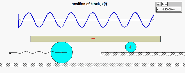
Question: Can you tell from the animation if the excitation frequency ω is smaller than or larger than the natural frequency ωn of the system?
Any questions?? Please ask/answer questions regarding this homework problem through the "Leave a Comment" link above.
For the acceleration of Block C do we add the accelerations that are contributed by A and B?
Yes I believe you would add the friction forces from each disk for the sum of forces in the x for C.
Instead of adding the accelerations I would recommend using the rigid body equations to relate the acceleration of C to the accelerations of A and B separately, giving you two more equations to work with.
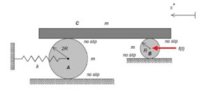
In the FBD do you assumer there are two normal forces? One between the ground and the disks, and another on the top the the disk that contacts with the bar?
Yes, but these normal forces end up cancelling due to taking the moment of the discs.
What is the best approach? To use three FBDs of the disks and bar or one big FBD of everything?
The best approach in my opinion is 3 separate FBDs it makes the question easier overall. It helps you look at them separately and determine the best approach. In terms of moments and force equations. As well as being able to take moments across the two contact points of the disk are easier if you use two separate disk FBDs.
If you use a FDB of everything it will make looking at the problem difficult. And youll need to account for the reactionary forces if you choose to do a single system and the frictional forces.
I also used three separate FBDs, as I was able to better asses each individual component to understand my next steps.
Yes, you do assume that since they are making contact with both surfaces
I would think so. I drew them on my FBD.
In what direction is the friction on the no slip points facing? I’m having issues understanding the relationship between the point of contact with the ground and the point with the bar C.
I always like to think of friction as opposing motion. I like to think about which way the point would move if it were able to slide without friction. Then friction acts in the opposite direction of that.
This gets kind of tricky when there is a no slip point though as the direction which the disk rolls is typically the direction that the friction force acts due to the nature of no slip points.
I believe as long as the frictions corresponding to the two different components that form a no slip point are equal and opposite in sign, the direction does not matter.
Whenever I try to draw FBDs with friction and a rotating disk, I draw the arrow representing the direction of the friction so that it points at the arrow representing the direction the wheel rotates. The two arrowheads meet. This is the strategy that works best for me and helps me avoid negative numbers. The friction acting on either surface would point in the opposite direction of the friction at the corresponding contact point on the wheel.
When I change the theta double dot for A and B into X double dot and plug that back in with the numbers my X double dot cancels, I don't fell like that's right but my process up that point feels ok. Is this right or did I make a mistake?
You should get the angular acceleration of A and B in terms of linear acceleration. If you have these relations correct it is possible you substituted angular acceleration for linear acceleration. The problem asks for the EOM in terms of x so you would need to substitute once again using that relation to get your variables in terms of x and not angular terms.
The x double dot did not cancel in my equation. I got an x double dot term in both the moments about A and B from their contact points with the ground that did not cancel.
Instead of taking the moment around the center of the disks, if you take the moment around the bottom of the disk, you're able to only have to deal with 2 friction forces, not 4.
The way I approached this problem is taking a moment about c for both disks and doing a sum of forces for the frictions on the bar.
In this system, analyzing the differential equation of motion is important to understanding its behavior. By deriving the equation and considering the forced response amplitude, you can gain insights into how external forces affect the system's dynamics.
I am still not understanding the direction of friction between the block and the top of the disc. Could someone explain?
The direction for the friction forces that you choose on the block is arbitrary. If you draw equal and opposite forces on the two disks you will be OK. As long as you do not set friction = mu*normal force, friction is a standard reaction force. Choose a direction and be consistent throughout, and signs take care of themselves.
During half of the cycle of oscillation, the friction force will point to the left, and during the other half it will point to the left. The math will take care of that if you are consistent throughout with your FBDs and sign conventions.
For his problem I recommend the following: Check out problem 6.A.3 in case that you have issues with how the friction is supposed to be placed on the system, and make sure that your coordinate systems are consistent so that whenever you transform everything back to X coordinate it's easy to do so.
I have found that the easiest way for me to understand and break down the system is if I align the friction arrow with the wheel's rotation direction, meeting at the arrowhead. However, the direction of the friction can be random, and as long as you are careful with your signs, you should get the same results.
This keeps confusing me to be honest. I know that the direction of friction force should be opposing motion, but given that the motion changes as a function of time I dont really understand which direction to put the friction force in when drawing the FBDs and setting up the equaitons.
Taking the moment about the non-slip points can help reduce the complexity of the resulting equations, as long as the parallel axis theorem is used. Aside from that, being careful with signs and directions is important, drawing multiple FBDs is important and can help generate equations.
If you take the moment from the center of the circle, there will 4 friction variables to deal with instead of two. It leads to having to add a bunch of different equations together to cancel out the friction terms which is very tedious. If I were to do this problem again, I would recommend taking the moment from the bottom no slip point so that only two friction forces would have to be dealt with. Also, keep in mind to differentiate the thetas of each disk since their radius is different.
Remember to rewrite the x-components of the EOM in terms of theta to get the kinetic and potential aspects of the equation in terms of theta and its derivatives.
Does the "forced response" of a system always only include the particular solution of the differential equation of motion by definition? By the setup of the problem, it the particular and complementary solutions have different angular velocities, so it would get tricky to combine the sin/cos terms to reach a single amplitude.
That's correct. The particular solution is from f(t) which is called the "forced response" of the system in the lecturebook. This external forcing term causes the response to be a certain frequency.
I have set up three equations -- 2 moments about no-slip points and a sum of forces in the x direction for the block. However, I need f(t) to solve these equations for the friction forces, and I don't know what w is. Can someone help me?
It sounds like you are on the right track. You should be able to keep w as a variable until part B.
Try to replace the friction forces in your net force of the block equations by solving for the friction in the moment equations.
Yes solving for friction with moment equations will give you more equations to simultaneously solve and match up the unknowns
w is given in part b of the find statement. It says "determine the amplitude of the forced response of block C when w is one-half the natural frequency of the system." Calculate the natural frequency using your EOM and then halve it.
To find the amplitude, the particular solution is useful when you take the absolute value because the sin term cancels out and you are just left with B.
I found it easiest to take moment about the center of the disks. Additionally, along with the moment, I also summed the forces in the x-direction.
Initially, this problem seemed very daunting due to the four friction forces acting in the system, but taking the moments about the point where the disks make contact with the ground simplified things a lot for me.
I found it pretty useful doing 3 separate FBD's of both disks and the bar. This allows you to set up a newton eq for the bar containing the frictions due to the disks, then setting up euler eq about the IC of both disks.
This is the same way I solved the problem. Taking advantage of the clear four step plan to break the problem down and then solving your resulting equations using a system of equations and taking advantage of the initial conditions.
Remember for Newton/Euler you always want to do individual FBDs instead of one large one. When doing the moments I made sure to assign positive theta in the CCW direction to avoid having negative signs during the kinematics step.
Would we need to have a different set of kinematics? one for each disk?
I took a moments for each of the disks about the contact points with the ground.
I had different Newton Euler Equations from the FBD and general kinematic equations!
I have set-up the kinetic and rigid body equations. How do I go about finding each of the friction forces?
I took moments for each of the disks about their contact points with the ground and I was able to solve for friction.
Try taking the moments of the disks, this will give you more equations to simultaneously solve
For this problem, example 6.A.3 is extremely useful in understanding how to set up the free body diagrams. Make sure to do an individual FBD for each of the disks and the block. This allows you to set up multiple equations to solve for the friction between each disk and the block.
One big hint is to take the moment of the disks around the non-slip contact point. This will allow for the normal forces to not have any affect, which will help simplify the equations.
Be careful about the signs of the friction forces when relating the block to the disks. I had the wrong relationship at first and it threw off the rest of my calculations.
By creating 3 Free Body Diagrams and taking moments around the contact points of the disks, it greatly reduces the amount of calculations nessasary for the problem. This is due to the problem specifying that these points do not slip against the surface.
For the question asked in the hints above ("Can you tell from the animation if the excitation frequency ω is smaller than or larger than the natural frequency ωn of the system?"), I believe that the diagram indicates that the excitation frequency is smaller than the natural frequency. This is because, as in the discussion on HW 6.J, as the disk moves to the left, the force is to the left.
Will I need a separate coordinate system for each disk?
Yes you would use different values to show the coordinates for each, and you would be able to define them in terms of theta.
Yes, this will make it easier to relate theta to X when it comes to solving.
In this question, it is really important to make sure that your signs are correct. In your FBDs, make careful note to draw your signs equal and opposite for forces that are found on more than one component. Besides that, taking moments around the no slip points on the disc and summing the forces on the bar should give you 3 eqns with 3 unknowns, and you can derive the EOM.
By taking the moment about each disk on a contact point, it allows us to eliminate two of the friction forces in our equations, making the solution much easier.
example problem 6c4 and 6c6 helped me figure out how to approach this problem super well.
Remembering that the disks are no slip on both contact points is extremely important when drawing the FBD
I found it helpful to setup moment equations about the contact points with the ground for each of the disks in this problem.
when setting up the problem I found it helpful to take the moment about the no slip point
Remember for this problem to properly account for the radii difference between the disks when converting between coordinate systems.
I suggest drawing three independent FBD's for this problem as you can solve for the friction forces and relate all of them to get the EOM. When drawing the friction forces be careful, example 6.A.3 is helpful for this portion.
When solving for this problem it would be helpful to note you need to begin by creating three Free Body Diagrams. After listing all forces, the free bodies can be used to solve for the recurring forces in each equation (the only summation in X needed is the one for the bar). Once solving for the frictional forces on the bar, the equation of motion can be easily derived.
For the second part, you need to interpret the effect that halving the frequency will do by calculating how that affects the final answer.
Remember the angular accelerations are different for each disk.
Hope this helps best of luck.
Remember to break the system down to 3 separate FBD with equal and opposite forces of f_A and f_B for ease of analysis. Doing so will also properly account for the radius difference
Using the three FBD's to solve in terms of the friction forces is a method to solve this problem. Additionally, for part (b), example 6.C.4 is helpful.
It is important to account for the different sizes of both disks when calculating the moment about a point.
I recommend having 3 separate FBDs for each component and naming the normal forces with the opposite but equal interactions in mind.
After solving this problem similarly to previous homework, I wonder is using work energy equations would simplify the process. In particular relating KE to x dot and theta dot.
To make the problem easier to understand I drew three separate FBD to show the different parts
Calculating the moment around the non-slip points can simplify the equations, provided the parallel axis theorem is applied. Additionally, attention to signs and directions is crucial. Creating multiple free body diagrams can aid in generating equations
When setting up the free body diagrams for both disk A and disk B, remember to take into account that each system experiences multiple normal forces as well as multiple forces of friction. This information is needed to solve for part A and part B of the problem.
For this problem, you must find the moment at the center of gravity of A and B. This will help you derive the EOM.
I used the moment at the instant center's of the ground's contact with the wheel and found any answer.
For me solving this problem, the most important thing was to write out every Newton and Euler equation for each body before I began solving for the EOM.
For this problem, multiple moment of inertia equations can be used to simplify the force equation in the x direction. Remember to take into account the signs when setting up the different moment of inertia equations.
What is the best way to determine the direction of friction in these problems?
I would look at the direction the disks are moving. Then I would image how the disks are rotating to determine which way friction would have to act to prevent the disks from slipping.
As Kenneth stated, look at the direction of motion for the disks. Moreover, you can look in the previous homework hints as a placeholder for understanding of the direction.
In part B of the problem, only the coefficient of A needs to be solved for in order to determine the amplitude of the system because the system is undampened. Therefore, the coefficient of B is equal to 0.
I would recommend keeping your work in variables until the very end, this helped me keep my work organized. Additionally the "concluding remarks" at the end of each daily schedule are always helpful to reference for relevant equations!
To connect the 3 separate equations of motion, is the best way to do so to write kinematics equations for accelerations?
Would It be possible to solve this problem using the Conservation of momentum seems like it would be possible?
For this problem, I would strongly suggest drawing free body diagrams for all three parts of the system. Then using the force and moment equations of these free body diagrams, you can relate each of these into one system EOM.
6.A.3 is helpful when figuring out the way friction interacts with the system. Remember that the bar must maintain a no slip point with the balls.
Ad with very similar past HW problems, I found it very useful to take the moment around the contact point and then relate if with the given equation and sum of forces.
I referenced example 6.C.1 to help in my analysis, specifically its method of finding the derivations for the particular solution as the math was quite similar. Splitting the components of the derived particular solutions led me to isolate the cos and sin components which helped me to find the necessary amplitude value for part B.
I found it helpful to take the moment around the top of each disk. Using 3 free bodies is also helpful.
Start with taking the moment around the contact point. This helps remove and cancel out unhelpful variables.