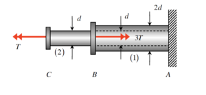
Problem statement
Solution video
DISCUSSION THREAD

Please post questions here on the homework, and take time to answer questions posted by others. You can learn both ways.
Problem statement
Solution video
DISCUSSION THREAD

You must be logged in to post a comment.
Should we start with the same strategy of creating separate FBDs for each part of the shaft with their individual forces or is it better to treat the shaft as one whole body when doing calculations?
You don't necissarily need to create an FBD of the whole body per se, but to determine the torque load in shaft 1 you must consider the torque loads placed on both shaft 1 and shaft 2 from connectors B and C respectively, which is basically looking at the whole body anyway (just with the wall joint cut off and considering what must be the reactive torque load in shaft 1 itself instead). For determining the load in shaft 2 you can simply consider it without consideration of the 3T force at B. This is due to the method of sections. Alternatively for shaft 1 you could solve for the entire body, find what the reactive force at A must be, and then use the method of sections to realize that the load in shaft 1 must be equal to the reactive force at A.
Thank you!
I found it easiest to just make 1 whole FBD and start solving.
Thanks for your insight!
would our torque for (1) and (2) be negative?
The sign does not matter in this case, they just want the magnitude of the torque.
For the ultimate torque, we just need the magnitudes, but when summing to find the torque in (1) for example, we need to pay attention to the fact that the two torques act in opposite directions.
The magnitude of the torque is the important part, but in terms of the signs for the torque it just depends on what way you set up your axes/force directions as well as how the torques relate to each other. Hope this helps!
Unless I have made a mistake, it seems that the stress in one component is negative but larger in magnitude than the other, although the other component's stress would technically be larger than the other due to the positive sign rather than negative. If this is correct, which should we count as larger?
Remember that for stress we are computing the magnitude of stress and do not care about the sign as much. But for which one is larger you take the larger magnitude.
I would start from the left side and see that the Torque in (2) is just equal to the applied torque on (2), and the Torque in (1) is equal to the applied torques on (2) and (1). Sum the torques then find the magnitude (abs value).
Is the torque load just the same as solving for the torque in each segment, ex solving for Fn as we have previously. Should we just write the value for Fn for this part.
Yes, they want the magnitude of torques in both components, just like when we solved for Fn.
Yes, Thomas and Ellie are correct. They want the magnitude of the torques for each of them.
You are solving for the magnitude of the torque, similar to some of the last homework assignments. The sign does not matter for your final answer. Hope this helps!
It's also important to remember that the formula for maximum shear stress uses radius and we are given the diameter.
Should we compare the max sheer stress between two each segments to get maximum sheer stress in the shaft? If AB is bigger than bc then we should use the AB value right?
By setting up the sum of moment equation for the whole shaft (ABC), I found out that the T_AB is negative. I am wondering whether this also indicate the direction of the stress. Since tau=T*ro/J, can I just get that the direction of the stress is also negative?
When solving for the torque in the first component, do you sum the total torques or just the the one acting at the end of the first segment?
I was able to solve it by doing them separately. This way you can see the torque load on each member and determine where the maximum shear stress is.
you add them for segment ab
I noticed that you could solve this answer by finding the torque separately and then at the end use method of sections to get all the information needed. Finally, input into the stress equation and find the tau.