| Problem statement Solution video |
DISCUSSION THREAD
Any questions??
Discussion and hints:
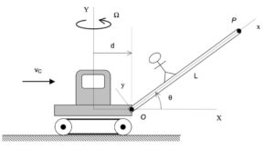
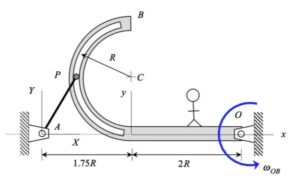
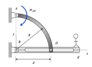
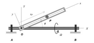
Your first decision on this problem is to choose your observer. Since an observer on the tube will have the simplest view of the motion of the particle P, attaching the observer to the tube is recommended. Also, attach you xyz-axes to the tube.
Next write down the angular velocity and angular acceleration of the tube. Based on what we have been doing up to this point in Chapter 3, hopefully it is clear that the tube (and observer) has two components of angular velocity: Ω about the fixed X-axis and θ_dot about the moving z-axis. Take a time derivative of the angular velocity vector to find the angular acceleration of the tube (observer).
Following that, determine the motion of the particle P as seen by the observer on the tube.
Use these results with the moving reference frame kinematics equation to determine the velocity and acceleration of the particle P.