| Problem statement Solution video |
DISCUSSION THREAD
Not collected.
Any questions?? Please ask/answer questions regarding this homework problem through the “Leave a Comment” link above.
| Problem statement Solution video |
DISCUSSION THREAD
Not collected.
Any questions?? Please ask/answer questions regarding this homework problem through the “Leave a Comment” link above.
Comments are closed.
How do we ensure the signs correctly represent a restoring force versus the driving force from the base?
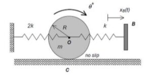
I guess to keep the signs correct, first choose one positive direction and stay consistent. Here, clockwise rotation and motion to the right are taken as positive. The restoring force from the springs should always act opposite to the displacement, trying to pull the disk back to equilibrium, so it gets a negative sign. The motion from base B is the external input, so it pushes the system and appears as the driving force term with a positive sign depending on the chosen direction. A simple check is if the disk moves right, the spring should pull it left.
I would recommend waiting until we cover this topic in class before working the homework.
Would summing moments about O or C be more efficient?
Summing moments about the COM of the disk (O) would isolate the frictional force.
Summing the moments about C removes the need to find the frictional force altogether.
I agree with your choice to sum the moments about the no slip point C. We want to ignore the friction force because it is an unknown. Since friction acts through point C, it causes no moment.
Summing the moments about C is the approach I took. Allows you to set it equal to Ic*(theta_doubledot), then just use the formula sheet for necessary info from there.
For EOM problem, I try to always do about the no slip point, but otherwise doing abou the center eliminates more forces which is helpful in other scenarios
I noticed that the mass of block B is small at 0.03 kg, but not zero. Does this mean the effect of the right spring is small due to being a result of B’s momentum? Would a larger value of B prevent the system from moving?
Two things. The mass of the base B is irrelevant. The motion of B is being prescribed, regardless of the mass of B.
The other this is that the problem statement says that the amplitude of the motion of B is given by b = 0.03 meters. It does not provide any number for the mass of B.
This is a good point to note! Mass is irrelevant since there is no value/variable for mass anywhere in the EOM equation, therefore it doesn’t effect this problem!
since the direction of theta is defined opposite to normal does that invalidate the right hand rule?
No.
This would not invalidate the right hand rule. Instead, it would just work opposite of how we usually see these problems. Instead of theta being defined as positive in the CCW direction, it is defined as positive in the CW direction, meaning that if we are taking the moment about a point and curl our fingers in the CW direction, even though or thumb points downwards, the moment is actual considered positive since our fingers are curled in the direction of positive theta.
Can the solution videos for all non graded homework be published so we can check our work once we finish them
Once we cover this material in class and give everyone a chance to work on the problems by themselves without the solution, we will release the videos.
How do I derive the kinematics for the motion of the disk and the angular vel. when the disk rolls? Also how do I write out the spring deformation here properly?
For the kinematics of the disk’s motion, you can start with xo = R*θ then derive to get vo = xo_dot = R*θ_dot and ao = xo_ddot = R*θ_ddot. The angular velocity of the disk is ω = θ_dot.
The spring deformation of the k spring should be expressed as the difference between the x and xB coordinates, where x represents the translation of the disk, because both the disk and base B move. Spring 2k is attached to a fixed wall so its deformation only depends on the x coordinate of the disk.
For part d, do we need to determine the time period T to sketch the graphs? If so, how would we do that?
We might not need the time period T for part (d). The plot is amplitude ∣A∣ versus excitation frequency ω. So we might only use the expression ∣A∣ and vary ω to sketch the graph.
When we solve for thetap = Asinwt, what does thetap actually represent?
I believe thetap in this situation represents the sine wave that describes the oscillation of the disk over time, with A as its amplitude, w as the excitation frequency, and t as time. It essentially just describes the motion of the disk in the long term.
I found it helpful to use the no-slip condition to relate translation and rotation early ( x=Rθ ), then write everything in terms of θ so the spring forces and motion equation stay consistent.
I was doing this homework and noticed that the movement/excitement of the base (=bsinwt) kind of acts like a “Force” term. Would it be acceptable to treat the base excitement like a Force term? When would it not be acceptable?
Yes it’s acceptable to treat the base excitement as a force term. Since the base connects through a spring, its motion just stretches or compresses the spring, which is like an external force. Now it wouldn’t be acceptable if the base is rigidly attached.
I do not believe we treat the base excitement as a force term. I believe this is because it acts with the spring it is attached too, and is not an independent force on its own. While solving, it should be 4k(x-xb) where xb is the base excitation term. xb is not a term on its own.
Since the displacement x_B(t) is happening at the base and not at the center of the disk, how does that motion translate into the force balance for the disk? When we write the spring force for the right side, is it f= k(x_B – x_O), or do we need to account for the disk’s rotation theta in that specific term as well?
The right spring force is based on the relative displacement between the base and the disk center, so write it as f = k(x_B – x_O). Since the spring is attached at the center, rotation does not directly change the spring length. Theta only comes in from rolling, where x_O = R theta, so f = k(x_B – R theta).
I found that choosing a consistent sign convention at the start and sticking to it for the rest of the problem made the set up much easier. Treating the spring forces in the opposite direction of displacement helped avoid sign errors, and any wrong direction assumptions worked itself out in the calculations.
I agree with this. I have chosen to stick with the (x-xB), and then just decide after if it is negative or positive. This has allowed for fewer errors, and I feel I am getting more used to familiar the calculations.
Why is friction not treated as a time-varying function?
I believe you can just find friction in terms of x and x” so it does not need to be in terms of x
I do not believe that friction should play a role in the final solution. If you take the moments at the contact point, friction will not be involved as it goes through the point and therefore has no moment. As such friction is ignored.
Friction is technically time-varying in reality, but since it is an unknown reaction force in this problem, it is not treated as a prescribed function of time. If it were given, then it would be treated as a function of time.
Because the disk rolls without slipping, the displacement of the center is x_o = R*theta. Allowing you to express both the changes in the spring and velocities in terms of theta putting it into one coordinate. Keep in mind the right spring stretches by R*theta – x_B(t).
I understand that the disk’s motion is being described using the angular coordinate θ, but I am still unsure how to correctly relate the spring deformation to θ. Since the disk rolls without slipping, the center displacement should be related to rotation by x_O=Rθ, but I want to confirm the sign convention because θ is positive clockwise. For the spring attached to the moving base B, should its stretch be written as x_B−Rθ, or does the direction of positive rotation change that expression?
When I solved this, (x_B – Rtheta) was how I wrote it, so I believe it would be the correct expression to represent this scenario.
I don’t fully get how to write the equation of motion in terms of θ. Do I treat this like rotation only, or do I also need to include the motion of the center of the disk?
Begin with finding the moment about C, which would be set up as Sum(M_c) = I_c * (theta_doubledot). From here follow our usual process for finding an EOM, use the moment of inertia equations, etc.
Write an EOM in terms of x or y and then use the appropriate x=Rtheta constraint to replace x/y in terms of theta. Different fbds will have different constraints depending on radius. Rotational motion at the center of the desk should be handled by Michael’s comment, where you just say that MC(if there’s a no slip point) or MO = I*thetadoubledot. I is going to include motion of the center of the disk, in addition to inertia due to displacement(parallel axis theorem)
When reviewing this question, I found it easier to use positive values for a clockwise rotation, is it easier to always use this notation… Is it easier to use this moving forward? Or switch depending on what a problem may look like?
Whatever works best for you, as long as you keep your notation consistent. If you have clockwise rotation be positive k, then you have to remember to adjust any moments accordingly. I personally like to keep clockwise negative, but then I just divide my EOM by -1. The important thing is that the left hand side of your EOM has the same sign for each term.
in order to get the EOM you have to find the moment about C, this will cancel the unknowns and allow you to complete the final equation