| Problem statement Solution video |
NOTE: Please complete ONLY Part (a). Do not work on Part (b).
DISCUSSION THREAD
Any questions?? Please ask/answer questions regarding this homework problem through the “Leave a Comment” link.
Discussion and hints
The four-step plan:
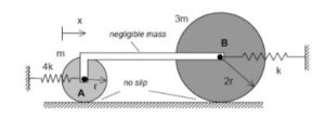
- FBD: It is recommended that you draw individual free body diagrams of each disk and of bar AB. Note that the mass of AB is negligible and that forces are applied at only two points (i.e., a two-force member). What does this say about the direction of the forces on the disks at A and B?
- Kinetics: Recommended that you use an Euler equation about the contact point of each disk since those are no-slip points for whose accelerations are directed toward the center of mass of each disk. Note that both of these two equations will involve the load carried by AB. You can eliminate that load from these equations, resulting in a single equation.
- Kinematics: Note that rigid bar AB insures that the velocities of points A and B are the same. How can this be used to relate the angular accelerations of the two disks? Can you see this kinematic relationship between the angular accelerations in the animation above? Please note that the angular accelerations of the two disks are NOT the same, although their centers have the same accelerations.
- EOM: Combine your results from Steps 2 and 3 to produce a single differential equation of motion (EOM) in terms of the x-coordinate.
Because the wheels are connected by a rigid bar, is there only one independent generalized coordinate, and should the two wheel rotations be related to x through the no-slip condition?
Due to the rigidity of the bar, if the center of mass of A travels x distance in the positive direction, the center of mass of B will also travel x distance. Therefore, it is not necessary to use more than one coordinate system. As for the no-slip condition, this gives you a point of contact where the velocity is known to be zero. This allows you to use the method of instant centers to relate x and the wheel rotation. Note that you must create a relation for both of the wheels.
When I solved I used only one generalized coordinate x for the wheels movement along x. But I used two different angle coordinates calling CW positive for a theta and phi (because they have different rotations). I then related those in my kinematics by recognizing they have the same velocity and using their respective ICs to get their velocity values and solving from there.
I solved the problem with two different x coordinates and two different theta coordinates. However, it is helpful to remember that, since the centers of mass of the disks are connected by the rigid bar, they move at the same speed x dot. Thus, your x systems for each will be the same, but, because the wheels are different sizes, the rotation of each wheel follows a different pattern. You can solve for theta using the instant center as the bottom of each wheel, since we are in a no slip condition for this problem.
Does changing the way we define the motion for theta, positive or negative, affect the overall EOM?
No, you can arbitrarily define this direction, though you may need to account for a sign change later in your calculations in order to obtain the correct EOM. However, it is easy to choose your positive orientation for theta such that the top of the disk is moving in the positive x direction.
For the larger wheel, should we treat its rotation as having the same sign convention as the smaller wheel and let the no-slip relation handle the sign automatically, or is it better to define each wheel’s positive rotation separately from the start?
I personally find it best to assume the rotations to be consistent with the positive translation. It makes the algebra much cleaner and avoids sign flipping errors in the EOM. If you assume theta is positive in the direction of rolling, x = r(theta) stays positive and you don’t have to worry about whether a force is opposing a negative rotation. I’d let the math do the work here and be sure your FBD is consistent.
What do you do about the friction forces at the bottom of the discs that are present in the Force equations?
The friction forces do not contribute to the moments of the contact points, so if you do the Euler Equations about the no slip points you shouldn’t have to worry about friction.
How can two wheels move at the exact same speed if their different sizes force them to spin at different rates?
The wheels have different radii. As they cover the same amount of ground, the must rotate at different rates to account for the different radii. v=r omega.
For the two force member AB, does this exert a force directed to the right at disk A and then a force directed to the left at disk B? I am having trouble picturing this realistically in my head. I feel like the two force member AB would exert a force to the right at A and another force to the right at B, but that would invalidate the properties of two force members, which say that the forces at each end must be in opposite directions. So how are they oriented?
I think we assume the bar is in tension and pulls inwards on both disks. Since they are internal forces they must cancel out. If they were both pointing right like you said the bar would be generating its own force, that is how I think about it.
I’m pretty sure the bar being rigid makes the spring partway simpler than it looks. For example, since both wheels have to move the same x distance, the 4k and k springs are basically just working in parallel. I just added them into a total 5kx restoring force in my EOM. Did anyone else do that, or is there a reason we should keep them separate in the Euler equations for Step 2?
You can assume they both point toward each other in tension, but ultimately their orientation shouldn’t matter since you can cancel them out like we did for friction in example 6.A.3
for anyone confused about the internal forces that act on A and B from the L shaped bar, I found it useful to solve the problem by leaving them in my Eulers equation for each isolated system, and then setting them equal to each other.
also, not 100% sure on how correct/useful this is, but:
I imagined the bar being pushed by an external force, which causes force of the bar the act in the positive x @ A and B.
ignore above comment it was wrong
is it possible to convert these two springs into one to solve this problem more efficiently? Or is it only possible by solving with the two springs as they are stated in the problem?
yes, you can. the springs have the same displacement because of the rigid bar. It doesnt matter that one spring is compressed and another is stretched. If you imagine dragging the bar to the right, the stretched and compressed spring push back to the left for a total “restoring” force of 5kx.
How do we mathematically reconcile the fact that these two wheels must travel the same linear distance while rotating at two completely different angular rates?
The two wheels (let’s say wheel 1 and 2) are able to travel the same distance while having different angular rates because they have different radii. If x is the distance, then x = r_1 * theta_1 = r_2 * theta_2. For x dot simply take the first derivative: x dot = r_1 * theta_1 dot = r_2 * theta_2 dot. And so on. Hope this helps.
If we define theta dot as positive in the clockwise direction, does that change the positive and negative directions of the moments?
As long as your signs for moments and angular acceleration consistently follow that clockwise convention on your FBD, the math should work out.
Given that the bar is rigid, if point A’s center of mass moves a distance x in the positive direction, point B’s center of mass must move the same distance. Does this mean we only need one coordinate system to describe the motion?
Yes, you only need separate coordinate systems when the motion in the coordinate axis direction of the two bodies is not the same.
Yes but you need 2 different rotational coordinate systems
How does the use of Laplace transforms affect the ability to solve more complex spring and vibration problems?
Laplace transforms can useful in solving EOMs of vibrations. For the simple forcings that we are considering here (sinusoidal), however, Laplace is an overkill. Like using a sledgehammer to drive in a thumbtack.
Since the springs and are attached exactly at the center of the wheels, both of their delta x are going to be purely in the horizontal direction, right?
Since the springs are in parallel and acting on the same line of action, can we just combine them when considering their effect on the system? As in, can we model the force acting on the system due to the springs as (k+4k)x?
When applying Euler’s equation about the contact point of each wheel, why is that point allowed to be used even though it is not fixed in space?
If you apply Euler’s equation to the point where the wheel is in contact with the ground, the velocity at that point is 0 because it is no slip. It does not have to be fixed in space, it just has to have no velocity
Recall that the “short form” of Euler’s equation (that is, not needing the second term) is valid for three different choices of reference point A:
* A = the center of mass
* A = a fixed point (zero acceleration…zero velocity is not valid)
* A = point on the body whose acceleration is parallel to the vector pointing from A to the center of mass of the body
A no-slip point of a wheel rolling on a fixed surface satisfies the third condition above. Therefore, you can use the short form of Euler’s equation for that point.
Since a rigid bar is used to join the 2 horizontally, their position, velocity, and acceleration in the x direction are all linked. This significantly reduces the number of equations needed to solve.
One concept I found tricky was dealing with the two-force member. I decided to sum the forces in the x direction and only consider the tension of the bar in the x direction. Is this the correct method, or is there a more accurate/easier method?
Since the bar is a two-force member the x-component of F_ab will be the same unknown magnitude for each disk and show up in each disk’s Euler equation, so you can set the two equations equal using F_ab. I don’t think you should need to sum forces in the x-direction if you use an Euler equation for each disk.
Since the bar has negliable mass, would the kinetics equation be equation to anything? Because F = ma and since m =0, wouldnt that means F = 0?
Please keep in mind that Newton’s second law says that the NET force acting on a body is equal to the mass times the acceleration. For the bar with negligible mass, the net force acting on the body is zero. That does not say that all forces acting on the body are individually equal to zero.
For the two disks of unequal radii connected by a rigid bar under no-slip conditions, how is it possible that their translational velocities are identical while their angular velocities are different?
Since the bar is rigid, the 2 centers move together, meaning they have the same translational velocity. But by using v = rω, we can see that the discs have different radii, thus, they must also have different angular velocities.
Since the bar is rigid and they both roll without slipping, should I treat the displacement and rotation of both wheels as identical in my energy equations?
Assuming the connecting bar is in tension makes it much easier to visualize. On Wheel B, both the bar force and the spring force point left when x is positive. If you take the moments about the instant centers, you can easily cancel out the bar force by adding the two equations together.
I still am kind of confused about how to solve this problem. Is there an easier way to break down the euler equation to get to the EOM? I know someone above mentioned Laplace transformations.
Follow our usual four-step plan:
1) FBDs
2) Newton/Euler equations
3) Kinematics
4) Produce the final version of the EOM
Laplace transforms do not come into play in deriving the EOM. It can be used to solve for the response. For our problems in this course, using Laplace transforms is an overkill.