| Problem statement Solution video |
DISCUSSION THREAD

Ask your questions here. Or, answer questions of others here. Either way, you can learn.
DISCUSSION and HINTS
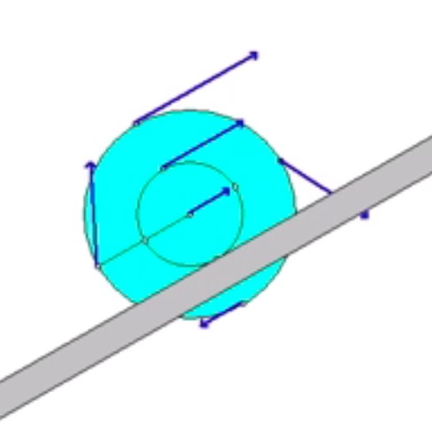
The animation below shows the motion of the wheel as it is being pulled up the incline. The animation shows the velocity of a number of points on the wheel. Think about the location of the instant center for the wheel as it rolls without slipping, and how this location affects the direction and magnitude of the velocities shown here.
Recall the following four-step plan outline in the lecture book and discussed in lecture:
Step 1: FBDs
Draw a free body diagram (FBD) of the wheel.
Step 2: Kinetics (Newton/Euler)
- Looking at your FBD above, which forces, if any, do work that is not a part of the potential energy of the system? Pay particular attention to the friction force at the no-slip point on the wheel – does it do work? How do you find the work done by the applied force F?
- Write down the kinetic energy of the wheel. Recall that the expression the KE for the planar motion of a rigid body is: T = 0.5*m*vA2 + 0.5*IA*ω2, where A is either the center of mass or a fixed point (fixed points include instant centers). So, in this case you can use either O or the no-slip contact point (let’s call that point C).
- Define your gravitational datum line. Write down the potential energy for the wheel.
Step 3: Kinematics
Use the IC approach to relate the velocity of the point on the wheel where the cable comes off (call that point A) to the angular velocity of the wheel. Or, instead, use the following rigid body kinematics equation:
vA= vC + ω x rA/C
Through a time integration of the relationship between the speed of A and the angular velocity of the wheel, you can determine the distance through which F moves.
Step 4: Solve
From your equations in Steps 2 and 3, solve for the angular velocity of the wheel at position 2.
For this problem, I found it useful to use the fixed contact point C for both kinetics and kinematic calculations, as it allows you to compute the answer to the problem without finding the velocity of the center of mass of the wheel. Also, by completing the integration of the speed of A and the angular velocity, I was able to calculate the distance traveled by the cord. I had to first calculate the wheel’s total change in angle through its travel to use that equation, however. I used the delta_theta = d/R_rotation relationship to find this change in theta value.
It is good to remember that the displacement at the point where the force acts is not the same as the displacement of the center.
confused on how to work integral is supposed to be setup in this case?
As you study your FBD for the wheel you see that the only non-conservative force that does work is the applied force F. The magnitude and direction of the force F are constant. Therefore, the work done by F is simply F times the distance over which the end of the cord moves.
As was discussed in class for this type of problem, the distance moved by the top point on the wheel is not the same as the distance that is moved by the wheel center O. To understand this, consider that the no-slip contact point is the IC for the wheel and that the speeds of points on the wheel are proportional to the distance from the IC to the point. You can use this to find the distance through which the end of the cord moves as compared to the distance through which O moves.
For step 3, I found using rigid body kinematics for the solution to be easier. Integrating across the velocity of A leads to a distance s that the outside cable moves, and solving for the angular velocity is simple from there.
Should we assume the surface the wheel is rolling up is smooth.
It says that the wheel does not slip on the surface. Because of that, the surface cannot be smooth, otherwise it would slip.
There is friction, but it doesn’t necessarily have any impact on the solving of the problem since it does no work on the system
For rolling without slipping, in the kinematics step, should we assume that the correct constraint for a_G = (R/2)*Alpha along the incline, or should we assume a sign for our alpha guess?
I assume that you are using the work/energy equation. If that is so, why are you writing down acceleration. For W/E you need only velocity.
I know that we should neglect friction because there’s no slip, but I’m not fully clear on this. I guess it’s because the friction is only static, but do we have to draw it on our FBD?
Your FBDs should include ALL forces, regardless of whether the force does work.
The friction acting at a no-slip point does work because it acts at a point that is not moving at that instant. The friction force itself is not zero; it just doesn’t do work.
When trying to determine the distance the force is applied for to find the work done by this force should it be 3d as that point is 3(R/2) from the contact point or should it be 2d as that point is 2(R/2) from the center of the disk? This was discussed in lecture last week as we were leaving and it was said to be 3d however this contradicts what many others are saying and I am unsure.
Let’s call the point on the wheel “B” where the cable comes off at the top, and the no-slip contact point C.
Since there is no slipping at C, point C is the IC for the wheel. Therefore, the speed of the center of the wheel O is omega*(R/2), and the speed of B is omega*(3*R/2). From this, you can see that point B is moving three times faster than O, and, as a result, the end of the cable moves three times as far as O moves. In the end, the work done by F is 3*d*F.
For this problem, I found it helpful, if not necessary, to set up a point A at F’s contact and C at the no-slip point. By finding the relationship between these values, you can figure out the change in distance needed for U, since you know how much distance the no-slip point “C” travels.