| Problem statement Solution video |
DISCUSSION THREAD
Not collected.
Question: Is the excitation frequency ω less than or larger than the natural frequency ωn for the parameters used in the animation below?
Any questions?? Please ask/answer questions regarding this homework problem through the “Leave a Comment” link above.
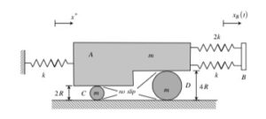
Are the two springs on the right effectively in parallel, meaning I should treat them as a single spring with stiffness $3k$ acting between the cart and the moving base B?
I believe that when you do your sum of forces in the x-dir they would be -2kx -kx, giving you effectively a single spring of stiffness 3k.
Keep it simple. Avoid using equivalent springs. Draw FBDs showing all you forces and use in the Newton/Euler equations.
I agree with this. It is usually better to draw small FBD’s for Newton/Euler, which means you wouldn’t be able to sum the springs as each wheel would have its own FBD
I believe you can do this since they’re both acting in the same direction and also both share the same change in x.
Yes, if they were acting in different directions you would not be able to sum them together.
When calculating the potential energy of the springs, how do I correctly write the compression of the right-hand springs in terms of (x – x_B)?
I believe both spring experience the same deformation because they are connected between the same two points. So their potential energy becomes: 1/2 k(x-x_B)^2 + 1/2 (2k)(x-x_B)^2
Why are you writing down the work/energy equation here? You should be using Newton/Euler to derive your EOM.
From your previous comment, we can combine the springs. So we can just use the potential energy formula for a spring which is 1/2kx^2 and plug in the values. So I believe it would be 1/2(3k)(x-x_b)^2
Why are you using potential energy in the N/E equations??
In a vibration question, you should always stick to the Newton-Euler method. We are trying to relate forces to acceleration here. Also, the Newton-Euler method gives a linear second-order differential equation, mx (double dot) + cx(dot)+kx, which is the EOM. The work-energy method will give a relationship between the velocities squared, which is NOT what we want. So that’s why you should mostly be thinking about using the Newton-Euler method.
This is not a problem where you need to find the potential energy of the springs. You want to use Newton/Euler equations at an instant as opposed to Work/Energy between two distinct states. All vibration questions should be just N/E since the math works out better.
The compression of the right-hand springs should be written using the relative displacement between cart A and base B. Since cart A moves x and base B moves x_B, the deformation is x−x_B or x_B−x, depending on sign convention.
Is base B assumed to be massless?
The mass of the base B is immaterial to deriving the EOM.
the mass of B doesnt matter to finding the EOM
I believe that because base B has a prescribed motion, its already defined as an external input rather than an unknown variable that responds to the system’s forces. Because its movement it forced by an external source, its mass is irrelevant.
Is it better to use a single coordinate system with rolling constraints, or write separate equations for the two rollers and cancel out variables?
I think the single coordinate approach with rolling constraints is probably the better way to go for this problem — once you establish that both rollers have their center velocity locked to x_dot/2 by the no-slip conditions, you can fold everything into one effective mass and just write one clean EOM. Writing separate equations for each roller would technically work but you’d end up with a system of equations with a lot of friction forces and reaction forces that you’d have to carefully cancel out, and I think there’s a pretty good chance of sign errors along the way. The Lagrangian/energy method with the single coordinate x probably saves the most time here since it sidesteps all those internal forces entirely.
The excitation frequency for the system shown in the animation is less than the natural frequency of the system because the motion is smooth and the system is able to respond. If the two were equal, the system would violently slide back and forth, and if the excitation frequency were larger, the system would not be able to react resulting in less motion.
I agree with your statement that the excitation frequency for the system is less than the natural frequency on the system. If the system were in resonance, we would see uncontrollable motion. If the system had a larger excitation frequency compared to the natural frequency, we would see 180 degrees out of phase motion.
Since both rollers roll without slipping with respect to the ground and the cart, can we treat their translational and rotational kinetic energy as an added “effective mass” contribution to the cart?
I believe you are correct. I think the “effective mass” should include both translational and rotational components.
You will not be dealing with kinetic energy in deriving the EOM. You need to use the N/E equations.
I would not recommend approaching the derivation of the EOM from an “effective mass” perspective. Keep it simple. Use the N/E equations along with kinematics, and the EOM will fall out naturally.
Is there a reccomended way to start handling the two no-slip constraints?
I included them in my newton equations and was able to solve like usual from there
I think the best way would be to have two separate friction forces on the tops of each wheel, then take sums of moments at the bottom contact points of each wheel. From there you have the motion of each wheel represented by the friction between it and the top bar.
I know that the two disks (about their COM) should be accelerating at half of the acceleration of the cart, such that alpha disk 1 (smaller one) = x double dot /2R. While I was able to work this out, I don’t feel confident that I would have spotted that relationship on an exam. Is there a more formal, overarching concept or a specific ‘check’ I should be looking for to recognize these kinematic constraints more intuitively?
I think that following the four-step plan naturally brings you along in your solution in a way that you will think of these things at the right time.
1) When you draw your individual FBDs of the two disks and the block in Step 1, you will want to define rotational coordinates (say, theta_1 and theta_2) for each disk.
2) These rotational coordinates are used in your Euler equations for the disks in Step 2.
3) At this point, you will recognize that you need to relate the 2nd time derivative of the two rotational coordinates theta_1 and theta_2 to the 2nd time derivative of x. You will use the no-slip points on the disks for these relationships, as we have done throughout the course, starting in Chapter 2.
“Intuition” is not something that comes instinctly. Intuition arises from first understanding of fundamental ideas, followed by the application of these ideas.
In part (d), the amplitude of cart A’s motion at Ω=2ωn is only
b/4 — smaller than the base amplitude b even though we’re operating above resonance. Students often expect large amplitudes near or above resonance. What physical mechanism causes the response amplitude to decrease as Ω increases well beyond ωn, and why does the cart move out-of-phase with the base in this regime?
At high frequency, the cart’s inertia keeps it from following the base, so the motion gets smaller. The negative response means the cart moves opposite the base, so it is out of phase.
Would it be ok to derive the EOM using both Newton’s laws and FBDs and energy, or does that get too complicated with the rolling constraints?
I do not see the role of the W/E equation in deriving the EOM for our problems in vibrations. Where will you use that?
I found it helpful to apply the no-slip conditions at both roller contacts to relate the cart’s translation x to each roller’s rotation, then combine their rotational inertias into an equivalent mass before forming the equation of motion.
Since you should use Newton, make the FBD include as much as possible
Based on the animation provided, the excitation frequency w appears to be less than the natural frequency w(n) because the motion of the system stays in phase with the base and follows it smoothly. If it was reversed and the w frequency was greater than the w(n) frequency, the r5esponse would be out of phase and the system wouldn’t track the base motion as it does currently.
I’m aware that the frictional force between the ground and the disks get cancelled due to taking the moment at the contact point. However, I just wanted to verify that in the case of block A moving right, the frictional force at the contact point also acts to the right to oppose the clockwise rotation. Is that correct?
Yes, it should be acting to the right. This is because if Block A is moving to the right, then the no-slip point of the disk should also be acting to the right because of the no-slip condition. If it moves to the right, then it will have a CW rotation. There would be two frictional forces here: one due to block A on the disks and the second due to the disks on block B.
For the 2 springs on the right side (k and 2k) can I simply combine them into one 3k spring?
I believe that you can, considering that they are both attached to the mass A and base B. However, to be on the side of caution I would still have them as separate when writing out the sum of forces in the x direction and only combine them when finding the general form of the EOM.
Could one also combine the spring on the left to make it 4k since all springs are attatched to the same mass, or does that logic not apply?
Yes, you are able to do so because they are moving in the same direction for this question.
Because the rollers have different radii but have the same m, does the mass contribution of roller D differ from roller C in the final EOM?
When you apply the no-slip conditions, the radii components should cancel, so the contributions should be the same !
Each roller has two no-slip conditions (with the ground and with the cart), this allows you to relate the cart’s velocity (x_dot) directly to each roller’s angular velocity. This means you can write all the kinetic energy terms in just terms of the coordinate x. Also since the radius of both rollers differs, the rotational values they have won’t be the same.
Just to make sure I understand how the x/xB concept works: is it true that if x>xB, the spring is in compression, and therefore the force on the block F=k(x-xB) is to the left? Can we pick either assumption of x>xB or x<xB to be true and determine the direction of the force?
yes, that’s how I’ve been thinking about it. If x>x_b the spring is compressed and pushes back to the left. and yeah, you can assume either x>x_B or x<x_B since the sign will correct itself in the end.
If x>xb makes the force move away from the wall, then you can say it’s in compression. Even if you make your force F=k(xb-X), the direction and math should work out
I understand that x describes the horizontal motion of cart A, but I am unsure how to correctly include the rollers’ motion in the effective inertia of the system. Since rollers C and D roll without slipping with both the ground and the cart, does each roller’s center move at a different speed than the cart
Yes, each roller’s center DOES move at a different speed than the cart. You know this because the rollers both have an angular acceleration, and they have a rotational and translational kinetic energy. The cart only has translational kinetic energy and potential energy from the springs. I think the different energies of the cart and rollers show that the rollers move at a different speed. I also don’t know how to correctly include the rollers’ motion in the system’s effective inertia..
How exactly do we relate the bar’s translation x to the angular motion of each disk if the bar does not slip on them, especially since the disks have different radii? Is the concept instant centers? Or relative motion?
You can relate the translation through the friction force that acts upon each disk and thus back onto the bar. By summing up forces in the x direction for the bar, the friction is related to the translation x.
What is the best way to make assumptions for solving natural frequency for problems like these? I find myself struggling to set up the question and solving in a consistent way
How would the “L-Shape” of the block effect this system’s motion if it were to come into contact with the right wheel? I understand that this won’t happen in this problem, but does anyone know how the problem/motion of the system would change?
For the exam and problems like these, is it good practice to have the Amplitude shortcut equation calculation memorized for both the no-damping system and the damping system? Or should I always work through it on my own to show work for credit?
It was stated in class that we will need to derive those equations on the exam anyway, so memorizing them may not be helpful
In order to get the keq you add the k and the 2k spring and then you can use 3k in the equation to get the natural frequency.
Are you combining the two springs into one equivalent spring? While that does work here, it has been advised not to do that in general, especially with the xB component now
Using the Newton-Euler method is always safe in order to obtain the EOM, especially when accounting for the spring forces of multiple springs. Since there are multiple in this problem, one has to draw them in the FBD and then include them in the x direction equation.
What I lowkenuinely found helpful was that for no slip, when the radii is different, specifically when there are multiple fbds, I found that making the EOM in terms of theta is the most helpful since the R value is different for the Newton vs the Euler.
*genuinely