| Problem statement Solution video |
DISCUSSION THREAD
Any questions?? Please ask/answer questions regarding this homework problem through the “Leave a Comment” link above.
Discussion
FOUR-STEP PLAN
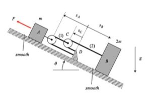
Step 1: FBD – Draw individual free body diagrams of A and B, along with an FBD of pulley C.
Step 2: Newton – From each FBD, write down the Newton’s equation for components along the incline. Recall that the pulley has negligible mass.
Step 3: Kinematics – You will need to use the cable-pulley system kinematics that we worked with earlier in the semester. Please review the material from Section 1.D of the lecture book to relate the accelerations of blocks A and B.
Step 4: Solve – Combine your equations from Steps 2 and 3 to solve for the accelerations of blocks A and B.
What given variables should the accelerations should be left in?
The two given parameters of F and m will be part of the answers, as well as the gravitational constant g.
Would it be okay to include T1 and T2 as the tensions of the cable? Or should they be solved out?
The two tensions are not “given” information; instead, you solve for these from the dynamical equations.
Are we allowed to use theta?
You are correct – the answer will be in terms of theta also.
how do u draw the fbd and fbd of what should it be blocks pulleys what
The rule of thumb for problems involving Newton’s 2nd law particle is that you draw an FBD for each particle. For this problem, it is therefore recommended that you draw one FBD each of particles A and B. I would recommend that the FBD for A to include the pulley that is attached to A.
Should our answers be the magnitudes of acceleration for A and B or vectors in i and j components?
It is always a good practice to write velocity and acceleration as vectors.
If we assumed up the ramp to be positive is it okay to put the vector form of our answer using this or does down the ramp need to be considered positive?
The choice of coordinate systems and positive/negative directions is totally up to you. It is important that you indicate what coordinates that you did choose so that the grader can follow your work.
I’m a little bit confused on how to calculate for the tension forces; I’ve solved for the d^2L/dt^2 for each of the two cables, but I’m not sure where and how to use them. Would the tension force be equal to the mass of the block times the d^2L/dt^2 of the cable, or is there something I’m missing?
Our recommendation is to follow the four-step plan:
Step #1: Draw the FBD(s).
Step #2: Write down the Newton equations for each FBD.
Step #3: Look at your equations from Step #2 – what kinematics do you need? In this case, you need to relate the acceleration of blocks A and B. You do this through the cable/pulley equations to which you refer above.
Step #4: At this point, it’s just math. You will have a set of algebraic equations written in terms of a set of unknowns. Just solve those equations. If it turns out that you have too few equations for the number of unknowns, then you have probably forgotten about some kinematic equations.
Does this help?
Should the final answers be left in terms of absolute acceleration or vectors?
In an earlier reply CMK says it always good practice to write it in vector form
I am a bit confused as to whether s_A is the distance from D to the pulley at A or the distance from the pulley at C to the pulley at A, if that makes sense, as in does the dashed line where s_A and s_B meet move?
For the length constraint would we count sc twice since there’s the top part of pulley c and the bottom part of the same pulley connected to D?
For each cable, add up the cable length in terms of the position variables sA, sB and sC. If sC appears twice in any equation then, yes, you are effectively counting it twice. Rely on your math!
When deriving the cable length equations you get that the acceleration one is a negative multiple of the other, but wouldnt that not make sense? since in the video they both accelerate in the same direction
Your statement that blocks A and B should be accelerating in the same direction is correct – they will either both be moving up the incline or both moving down the incline, depending on the size of the applied force F.
I am supposing that you have written down the constraint equations for the two cables in terms of the position variables sA and sB, and that you found sA_ddot and sB_ddot to have opposite signs. Note that is consistent with your first observation that A and B move in the same direction; that is, if they are accelerating up the incline, then sA_ddot > 0 and sB_ddot < 0.
Does this help?
Should each component of the tension be broken up into sin and cos (i.e. T1(costheta + sintheta) because the system is on an inclined plane or can it be viewed as just the horizontal plane?
I recommend that you choose an x-axis that is aligned with the incline. Then you can sum forces in the x-direction and not need to deal with trig. Same way with the acceleration terms – only in x and no need for trig.
Make sense?
There two sperate cables for each pulley hence there will be two kinematic length equation you need to make solve for the unknowns.