| Problem statement Solution video |
DISCUSSION THREAD
Not collected.
Low and high frequency excitations: ω < ωn and ω > ωn
- The top animation below shows the particular solution for the response corresponding to an excitation frequency that is less than the natural frequency. For this range of excitation frequencies, the response is in phase with the base motion.
- The lower animation is for the excitation frequency larger than the natural frequency. As expected, this response is 180° out of phase with the excitation.
Are these phase differences apparent to you as you view the animations?
Any questions?? Please ask/answer questions regarding this homework problem through the “Leave a Comment” link above.
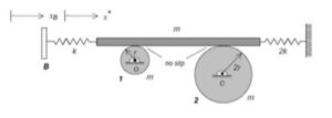
For this problem I found it helpful to sum the moment about the center of each of the disks as this allows the frictional forces at the nos slip points to be related.
If the discs are rotating clockwise, is it safe to assume the frictions acts to the left on the top of the disc?
Yes, because if the disk rotates clockwise, the top contact point moves to the right. Friction always opposes the relative motion, so the friction force on the disk acts to the left.
As mentioned earlier is our discussion, do not spend time trying to figure out the direction of friction forces due to no-slip contacts – over half of one cycle, the friction force will point to the left, and over the other half of the cycle it will point to the right.
What is important is to assume a direction for any given friction force (arbitrary). Be sure to use Newton’s third law in drawing equal and opposite friction force on the opposing surface at the contact. Math will take care of itself. Friction at points of no-slip contact is like any force of reaction – you do not need to know the direction when drawing the FBD.
Yes I would say it’s safe to assume that
I believe it depends on the situation given. For a pinned disk, friction will oppose the axial rotation. For a free moving disk, the friction will oppose the direction the disk is moving in.
The direction of friction usually does not need to be determined beforehand. I usually just draw it in the direction of positive motion. When taking moments, if the problem has a no-slip condition, I take moments about that point so that it eliminates that variable. Otherwise, it will take extra equations and effort to figure out what the value of the friction is. Then, Ic = Io + m(d^2).
dont we need to know b and w to solve this? or am i mistaken
Leave your answer in b) in terms of b and omega.
When setting up the EOM, I found it helpful to use conservation of energy to verify the answer obtained from the Newton-Euler approach.
Should the FBD be drawn separately or together for each body?
Recall that when using the N/E equations, you need individual FBDs of the bodies in the system.
Would the phase difference change the amplitude of B’s motion? Is the in-phase amplitude double that of the out-of-phase?
I don’t think the phase difference changes the prescribed amplitude of block B’s motion, because x_B=bsin(ωt), so the amplitude of B is always b.
No, the phase difference would not change the amplitude of B itself because B’s motion is prescribed. Its amplitude stays b.
The phase difference mainly changes how much the left spring stretches. If the bar and B move together, the spring stretch is smaller. If they move opposite directions, the spring stretch is larger.
So I would not say the in-phase amplitude is automatically double the out-of-phase amplitude. It depends on the bar’s response.
For the left spring, should its deformation be written as x−x_B, since point B is moving, while the right spring deformation is just x? I want to make sure I’m handling the prescribed motion x_B=bsin(ωt) correctly in the EOM.
Yes I believe that is correct
Yes that is right, because we want it to be in terms of change in x, and since B is moving, the change in x would be (x-x_B).
Would using kinetic energy be simpler here than writing separate torque equations for each disk, since the disk contact forces can be avoided?
I was thinking yes because the biggest advantage is that you don’t have to straight out solve for the contact or friction forces at the disk-bar overlaps.
The W/E equation is a nonlinear, first-order differential equation in speed. Not easy to solve. The N/E equations produce a second-order linear differential equation. The solving of this kind of differential equation has been the focus of our work here in this course. This is a highly recommended approach here.
For vibration problems, usually you have to always use the Newton-Euler Kinetic method. So as soon as you see a vibration problem, my first instinct is to always have my Newton-Euler equations ready after the FBD.
In I if the driving frequency was equal to the natural frequency would the particular solution change?
The response is actually undefined when omega = omega_n.
I believe in the lecture book we are given a graph relating the two frequencies, and there’s a discontinuity where they equal each other. My professor said that’s the point where singers can break glass with their voice, aka it usually leads to an explosion
Yes. If the driving frequency equals the natural frequency, the usual assumed particular solution Asinωt no longer works because the denominator becomes zero.
In J, when calculating the potential energy why is the springs stretch defined as 1/2 x instead of the full x
Why do you say that the stretch is x/2? Also, why are you finding the potential energy? You should be using the Newton/Euler equations, not work/energy.
Since Block B just has a prescribed motion and the problem states the bar has a mass of m, shouldn’t we be drawing the FBD for the bar instead of the block? I’m planning to draw FBDs for Disk 1, Disk 2, and the Bar to set up my Newton-Euler equations, but I wanted to see what others are doing.
Yes, your plan is correct. Block B has a prescribed motion so its kinematics are given so you are good on that.
I am assuming they meant the bar and not the block. You need the FBD of the bar for the coordinate system of x, whereas we can not create an FBD of the block since it’s a forced oscillation.
Yeah, I agree. Since x_b is prescribed, block B is just the input motion, not a dynamic body we need to solve.
I’d draw FBDs for the bar, Disk 1, and Disk 2. The block FBD would only show the spring force from x_b, but it would not add a useful equation of motion.
Since the block moves to the right, this forces the disks to rotate clockwise. Does this mean we can assume the friction forces on the block from the disks are to the left? Or how would we determine the direction of these friction forces?
We can initially not determine the direction of the friction force. Instead, we can choose a consistent positive direction (for example, the rod moves to the right), and then write the equation.If the direction you assume is incorrect, then the value of this friction force during the solution process will be negative.
I found it helpful to first relate the bar’s translation x to the angular motion of each disk using the no-slip condition, then rewrite the system as one equivalent mass-spring problem in terms of x.
this, along with assuming directions first definitely made the setup easier. I noticed that trying to figure out friction directions visually was confusing.
I made 3 separate FBD’s for each unique component. For these disks, would the friction force be modeled as counteracting the axial rotation? In this past, we would model friction counteracting against the motion of an object, however, in this problem, the disks are pinned. Does this mean the rotational speed would be opposed by the friction instead?
While doing HWs, for me setting up Newton-Euler equations and sticking to a consistent coordinate system is easier than guessing the “correct” physical direction of friction on the first try.
I found it helpful to assume a direction for the friction forces when drawing my FBDs and then solve it to determine the sign. This made setting up the equation for the Newton/Euler method very straightforward especially because it’s hard to determine the direction of friction at different points by just looking at the figure
After studying these oscillation problems, I was curious if there would be a way to do these types of problems with work/energy kinetics rather than just Newton’s laws. Although it may be more complicated, would the math be easier to do since you can combine more components into your system?
The Newton-Euler method relates forces to acceleration, whereas the work-energy method relates velocity to displacement. For most of the vibration problems, we need the first one. Also energy is a scalar quantity, whereas vibration problems are very direction-dependent. Also, the work-energy equation tracks the total work done over a distance, but in a vibration problem, we need to model a time-varying force through our EOMs. So that is why whenever you see a vibration problem, you should usually stick to the Newton-Euler method.
The no-slip conditions of this problem allow us to establish a direction for friction forces which we will validate through calculations. I’m confused when trying to understand friction force direction at each moment is its ability to reverse during movement between different states. The equations provide the solution to determine when friction force changes direction during a complete cycle of motion, which needs to be followed instead of using intuitive methods.
No slip basically means that the relative velocity between those two points is equal to zero. In other words, both the points have the same velocity. So if the first point has a zero velocity, then the other one will have a zero velocity. If the first point has a velocity say equal to 6 m/s, then the other point will also have a velocity equal to 6 m/s.
To clarify the meaning of the no-slip condition. It doesn’t always mean the velocity is zero at the contact point; it means that it is equal to whatever it is in contact with. So in this case the no slipping against the block just means that the velocities are equal. In most cases the disk is rolling on the ground so it is zero in that case relative to the ground. Is this the correct form of thinking?
yes, that’s how I’ve been thinking about it too. the no slip condition just means the velocities at the contact point are equal, not zero necessarily. so in this case, the disk’s rim velocity should match the bar’s velocity i believe
yes, that’s how I’ve been thinking about it too. the no slip condition just means the velocities at the contact point are equal, not zero necessarily. so in this case, the disk’s rim velocity should match the bar’s velocity i believe
So is it correct to assume that this means there is not extra velocity at the contact point due to the rolling, and the velocity should just be assumed to be whatever it is touching
Yes, I believe it is correct to assume that the velocity of the contact point is equal to whatever it is currently touching. That is not to say that the rotation of the wheel is not the cause of the velocity/motion, but just that the mass it is contacting and the contact point will have the same velocity.
This is correct! When two objects are in contact and “rolling without slipping,” the fundamental rule is that there is no relative motion between the two surfaces at the exact point of contact.
Use the no-slip condition to relate the bar’s translation to the disks’ rotation. Because the bar rolls without slipping on both disks, the velocity of the contact point must match. That gives you relationship such as v = r*theta_dot. This lets the kinetic energy be expressed in terms of just the coordinate x.
Will these types of problems (EOM) always start with N/E equations and separate FBDs, and then bring in another method (such as momentum for some examples) if needed?
To my understanding, these EOM problems will always involve drawing your FBD(s), writing the Newton equations (Euler when rotation or moment is involved), and combining to solve (along with kinematics). This method is simple compared to W/E, so it is always recommended to use it.
Yes, always go with N/E for these EOMs. I would also like to point out for rotating disks, always use sum of the moments, and for bodies like bars that do not rotate, then you use the newton equations, sum of the forces.
I understand that the bar’s displacement x is the main generalized coordinate, but I am still confused about how the no-slip condition affects the angular motion of the two disks. Since the disks have different radii r and 2r, would their angular velocities be related to the bar velocity by different constraints?
Yes. Because the disks have different radii, the angular velocities will have different magnitudes. The velocities are proportional to their respective radii, so disk 1 of radius r will have omega1 = xdot/r, and disk 2 of radius 2r will have omega2 = xdot/(2r). The xdot values are consistent across each disk (no slip) but the angular velocities are not.
I got really confused with how friction works here… What is the best way to evaluate friction with an oscillating platform?
The nice thing about these problems is you don’t need to worry about getting the right direction of friction as long as it is equal and opposite for each FBD. For example, on the small disk, you can have friction at the top be left or right. If you draw friction pointing to the left on the top of the small disk, then the friction on the bar due to the small disk has to be to the right.
As long as you pick one direction and stay consistent in the equations, I believe that the specific direction you pick does not matter.
In this problem, the left spring is attached between the bar and a moving block B, so its force depends on the relative displacement x−xb. For exams, should we expect to consistently model springs between two moving bodies this way, rather than just springs attached to the ground? And should we expect to apply this approach to general two-mass systems as well?
Pertaining to the friction, it does not have to be included in the x direction because it is being cancelled out by the top bar in this situation, correct?
Friction should be included in the FBD’s since it is what enforces the no-slip condition between the bar and disks. Even though the friction forces cancel out later, they are also needed initially to correctly set up the N/E equations.
The non-slip conditions of this problem mean that one can use the fact that the bar rolls without slipping on the two disks and use translation to relate the bar to the disk rotation and say that the velocity at the contact points must be equal.