
Laser cutting works by directing a laser together with a motion control system to follow a pattern to be cut out of a sheet of material. The laser either melts, burns, vaporizes away the material, or is cut by a jet of gas, leaving a smooth surface finish where cut.
- The RDWork v8 cutter that we have can handle sheets that are 24 inches x 36 inches that are up to 0.125 inches thick. Follow this link to see ordering options for acrylic material that is most commonly used.
- Formats that can be sent to this cutter include:
- Vector format: .dxf, .ai, .plt, .dsb
- Bitmap format: .bmp, .jpg, .png, .mng
HOW TO SEND A JOB TO THE LASER CUTTING QUEUE
- Open a ticket in the Boilermaker Lab Queue
- Attach the DXF file to be cut (upload is much faster if you can .zip the file)
- Add a note indicating
- What material will be used
- If there is data to be engraved include
- the color of the items to be engraved (otherwise everything will be cut through the depth of the material)
- specify the depth of the engraving
HOW TO PREPARE FILES FOR SENDING TO THE LASER CUTTER
From NX
- Create the shape that you want to be cut as a sketch in NX. Nothing else, like solid geometry should be in the .prt file.
- The sketch should be a closed loop to ensure that the profile will easily detach from the sheet that it was cut.
- If you have any construction lines in your sketch – DELETE THEM! Even if they are hidden on a layer they will appear in the exported file!
- If you want shapes or lines engraved (cut only partially through the material thickness) create another sketch for those items.
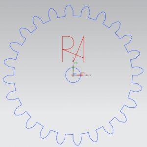
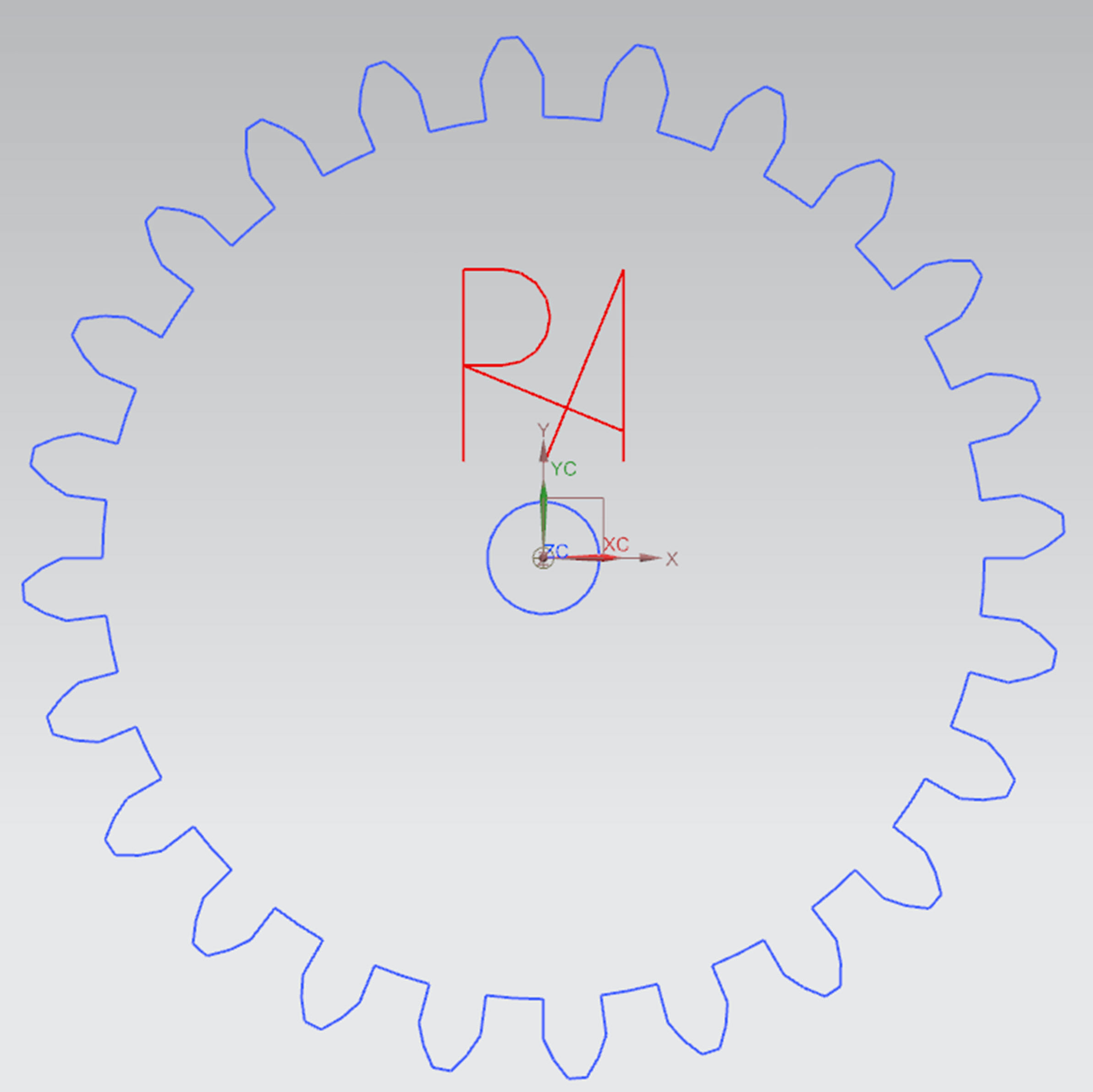
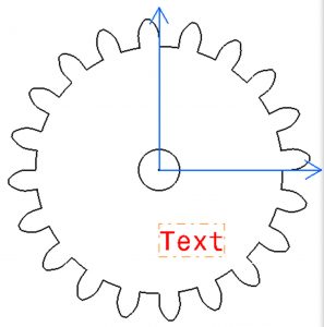
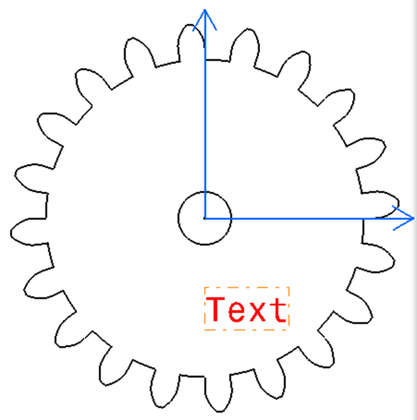
- Change the color of the engraved lines to be a different color than those to be cut, as shown in the example to the right.
- Click on the sketch
- Choose the Edit Display icon
- Click on the current color
- Choose Red, ID 186
- Press OK
- Change the color of the engraved lines to be a different color than those to be cut, as shown in the example to the right.
- Set the view that will show the sketch flat to screen to be active.
- Under Model Views in the Part Navigator double-click on the name of the view to orient the sketch. By default the Trimetric view is set to the Work view.
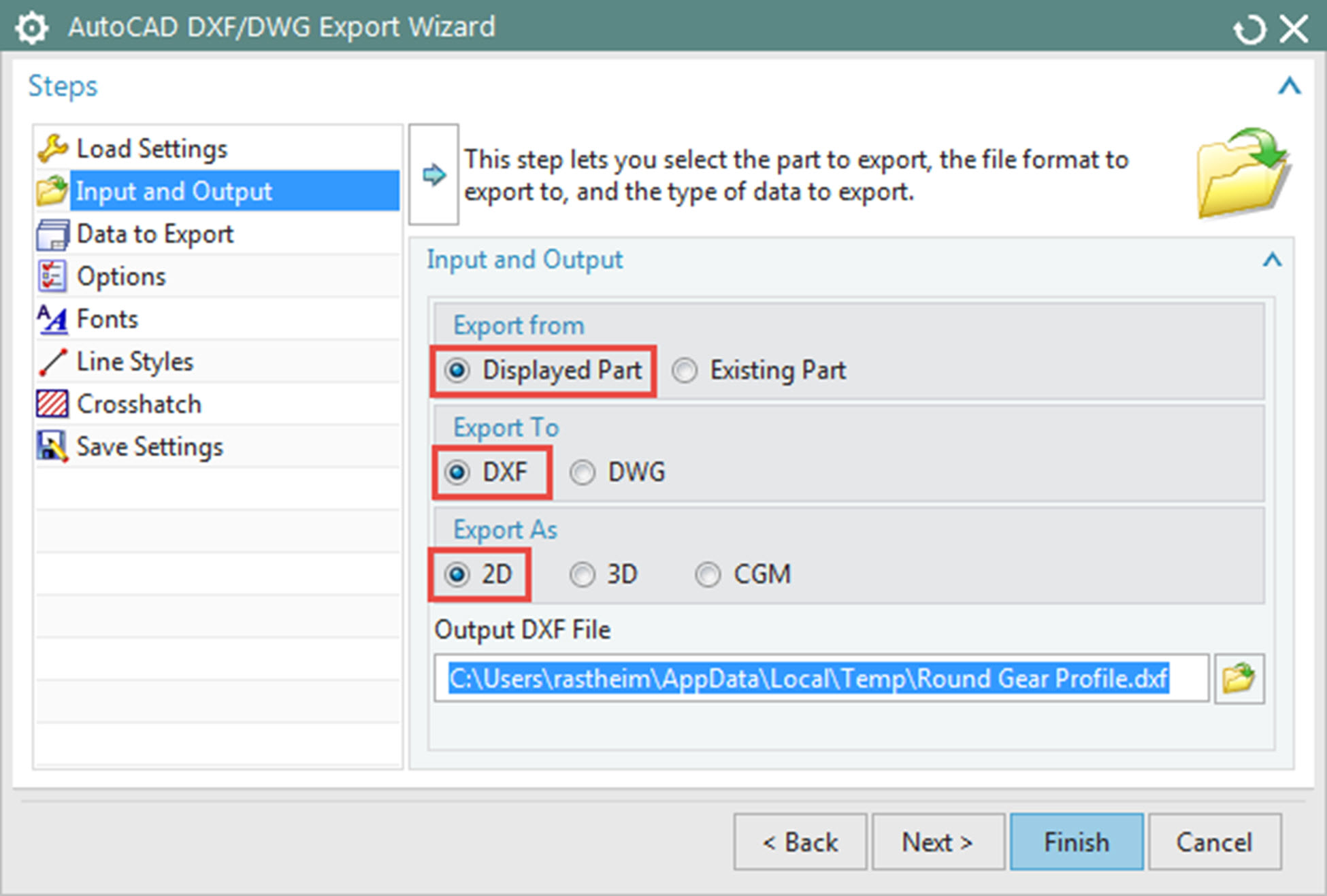
- From the File menu select Export then AutoCAD DXF/DWG
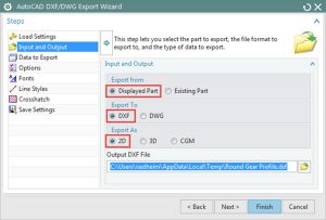
- From the Input and Output section choose
- Export from Displayed Part
- Export To DXF
- Export As 2D (important to check this option!)
- Set the path to where you want the file written
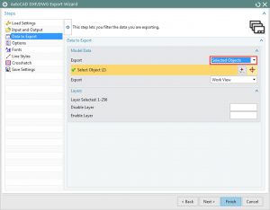
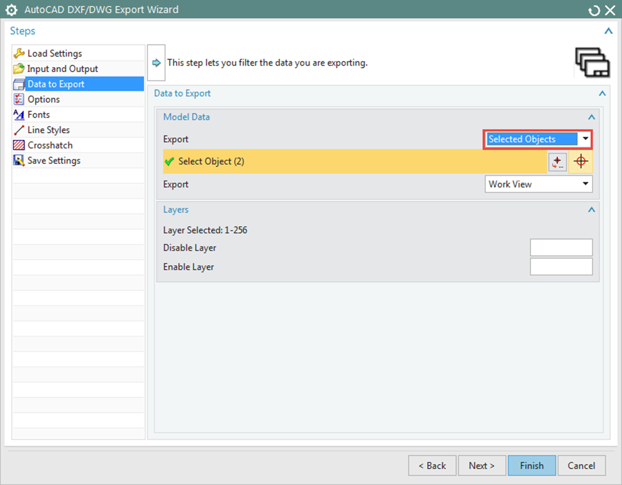
- On the Data Export section choose
- Export Entire Part
- Export Work View
then proceed to select all sketches to be exported to the DXF file.
- On the Options section set
- DXF/DWG Revision to 2004
- Export Spline As Spline
- Check the option to Remove Overlapping Entities
- Press Finish
- From the Input and Output section choose
From CATIA V5
- Create the shape that you want to be cut as a sketch in V5. Extrude that shape to create solid geometry.
- Create a new Drawing file. The size of the sheet does not matter.
- From the Insert menu choose > Views > Projections > Advanced Front View.
- Ensure that the scale is set at 1:1 and Press OK.
- Switch windows to the 3D model geometry and select a plane that will orient the sketch f
 lat to the drawing page.
 - Click outside of the view border to place the view on the drawing.
- Right click on the view border or the view name in the drawing tree and choose Properties
- Uncheck the Display View Frame option and Press OK
- Delete the view label showing the scale by clicking on it and pressing the delete key.
- Text can be added using the Text tool. Change its Properties so that the Color of Lines and Curves is different than the color of the lines to be cut, as shown in the iamge on the right.
- Export by selecting File > Save As and set the Save as type to dxf (*.dxf)
If you have any additional information, comments or udpates about the above information, please contact rastheim@purdue.edu