
One theory that is used for the prediction of failure in a ductile material is the maximum shear stress theory (MSS). The basis of this theory is that failure will occur when the maximum shear stress exceeds the maximum shear stress that exists for yielding in a uni-axial test. Consequences:
- The failure boundary corresponds to|τ|max,abs = σY/2.
- In the principal stress plane (σP1 vs. σP2 plane), this failure boundary is the hexagonal region shown to the right.
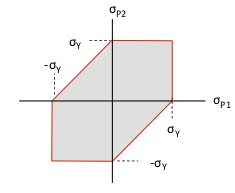
The hexagonal-shaped boundary above is the locus of points in the principal stress plane that corresponds to constant values of |τ|max,abs . How does this locus of points link back to the Mohr’s circle plane? The animation below shows how the Mohr’s circle changes as we move around on this hexagonal-shaped boundary between safe and failure.
Observations
- In quadrant 3 of the principal stress plane, Mohr’s circle is in the left-half plane with the failure boundary prescribed by σP2 = –σY .
- In quadrant 1 of the principal stress plane, Mohr’s circle is in the right-half plane with the failure boundary prescribed by σP1 = σY .
- In quadrant 4 of the principal stress plane, Mohr’s circle has a constant radius R = σY/2 .
- At the beginning and end points of the above animation, the failure boundary is located at σP2 = σP1. As discussed earlier in the course, this corresponds to a state of “hydrostatic” stress. This corresponds to a Mohr’s circle with a zero radius. Such a state of stress has zero in-plane shear stress.